6.1 All structural members, assemblies or framework in a building, in combination with the floors, walls and other structural parts of the building shall be capable of sustaining, with due stability and stiffness the whole dead and imposed loadings as per Part 6 ‘Structural Design, Section 1 Loads, Forces and Effects’ of the Code, without exceeding the limits of relevant stresses specified in this Subsection.
6.2 Buildings shall be designed for all dead and imposed loads or forces assumed to come upon them during construction or use, including uplifts or horizontal forces from wind and forces from earthquakes or other loadings. Structural members and their connections shall be proportioned to provide a sound and stable structure with adequate strength and stiffness. Wooden components in construction generally include panels for sheathing and diaphragms, siding, beams, girder, columns, light framings, masonry wall and joist construction, heavy-frames, glued laminated structural members, structural sandwiches, prefabricated panels, lamella arches, portal frames and other auxiliary constructions.
6.3Net Section
6.3.1 The net section is obtained by deducting from the gross sectional area of timber the projected area of all material removed by boring, grooving or other means at critical plane. In case of nailing, the area of the prebored hole shall not be taken into account for this purpose.
6.3.2 The net section used in calculating load carrying capacity of a member shall be at least net section determined as above by passing an imaginary plane or a series of connected planes transversely through the members.
6.3.3 Notches shall be in no case remove more than one quarter of the section.
6.3.4 In the design of an intermediate or a long column, gross section shall be used in calculating load carrying capacity of the column.
6.4 Loads
6.4.1 The loads shall conform to those given in Part 6 'Structural Design, Section 1 Loads, Forces and Effects' of the Code.
6.4.2 The worst combination and location of loads shall be considered for design. Wind and seismic forces shall not be considered to act simultaneously.
6.5Flexural Members
6.5.1 Such structural members shall be investigated for the following:
a) Bending strength,
b) Maximum horizontal shear,
c) Stress at the bearings, and
d) Deflection.
6.5.2 Effective Span
The effective span of beams and other flexural members shall be taken as the distance from face of supports plus one-half of the required length of bearing at each end except that for continuous beams and joists the span may be measured from centre of bearing at those supports over which the beam is continuous.
6.5.3 Usual formula for flexural strength shall apply in design:
fab=ZM≤fb
6.5.4 Form Factors for Flexural Members
The following form factors shall be applied to the bending stress:
a) Rectangular section — For rectangular sections, for different depths of beams, the form factor K3 shall be taken as:
K3=0.81(D2+55000D2+89400)
NOTE — Form factor (K3) shall not be applied for beams having depth less than or equal to 300 mm.
b) Box beams and I-beams — For box beams and I-beams the form factor K4 shall be obtained by using the formula:
K4=0.8+0.8y(D2+55000D2+89400−1)
where
y=p12(6−8p1+3p12)(1−q1)+q1
c) Solid circular cross-sections — For solid circular cross sections the form factor K5 shall be taken as 1.18.
d) Square cross-sections — For square cross sections where the load is in the direction of diagonal, the form factor K6 shall be taken as 1.414.
6.5.5 Width
The minimum width of the beam or any flexural member shall not be less than 50 mm or 1/50 of the span, whichever is greater.
6.5.6 Depth
The depth of beam or any flexural member shall not be taken more than three times of its width without lateral stiffening.
6.5.6.1 Stiffening
All flexural members having a depth exceeding three times its width or a span exceeding 50 times its width or both shall be laterally restrained from twisting or buckling and the distance between such restraints shall not exceed 50 times its width.
6.5.7 Shear
6.5.7.1 The following formulae shall apply:
a) The maximum horizontal shear, when the load on a beam moves from the support towards the centre of the span, and the load is at a distance of three to four times the depth of the beam from the support, shall be calculated from the following general formula:
H=IbVQ
b) For rectangular beams:
H=2bD3V
c) For notched beams, with tension notch at supports (see 6.5.7.3):
H=2bD123VD
d) For notched at upper (compression) face, where e > D :
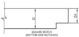
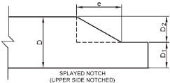
H=2bD13VD
PART 6 STRUCTURAL DESIGN — SECTION 3 TIMBER AND BAMBOO: 3A TIMBER
e) For notched at upper (compression) face, where e<D:
H=2b[D−(DD2)e]3V
6.5.7.2 For concentrated loads:
V=9l[2+(x/D)2]10C(l−x)(x/D)2and
For uniformly distributed loads:
V=2W(1−l2D)
After arriving at the value of V, its value shall be substituted in the formula:
H=IbVQ
6.5.7.3 In determining the vertical reaction V, the following deductions in loads may be made:
a) Consideration shall be given to the possible distribution of load to adjacent parallel beams, if any;
b) All uniformly distributed loads within a distance equal to the depth of the beam from the edge of the nearest support may be neglected except in case of beam hanging downwards from a particular support; and
c) All concentrated loads in the vicinity of the supports may be reduced by the reduction factor applicable according to Table 12.
Table 12Reduction Factor for Concentrated Loads in the Vicinity of Supports [Clause 6.5.7.3 (c)]
Distance of Load from the Nearest Support
1.5 D or Less
2 D
2.5 D
3 D or More
(1)
(2)
(3)
(4)
(5)
Reduction factor
0.60
0.40
0.20
No reduction
NOTE — For intermediate distances, factor may be obtained by linear interpolation.
6.5.7.4 Unless the local stress is calculated and found to be within the permissible stress, flexural member shall not be cut, notched or bored except as follows:
a) Notches may be cut in the top or bottom neither deeper than one-fifth of the depth of the beam nor farther from the edge of the support than one-sixth of the span;
b) Holes not larger in diameter than one quarter of the depth may be bored in the middle third of the depth and length, and
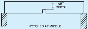
c) If holes or notches occur at a distance greater than three times the depth of the member from the edge of the nearest support, the net remaining depth shall be used in determining the bending strength (see Fig. 1)
FIG. 1 NOTCHED BEAMS
6.5.8 Bearing
6.5.8.1 The ends of flexural members shall be supported in recesses which provide adequate ventilation to prevent dry rot and shall not be enclosed. Flexural members except roof timbers which are supported directly on masonry or concrete shall have a length of bearing of not less than 75 mm. Members supported on corbels, offsets and roof timbers on a wall shall bear immediately on and be fixed to wall-plate not less than 75 mm × 40 mm.
6.5.8.2 Timber joists or floor planks shall not be supported on the top flange of steel beams unless the bearing stress, calculated on the net bearing as shaped to fit the beam, is less than the permissible compressive stress perpendicular to the grain.
6.5.8.3 Bearing stress
6.5.8.3.1 Length and position of bearing
a) At any bearing on the side grain of timber, the permissible stress in compression perpendicular to the grain, fcm , is dependent on the length and position of the bearing.
b) The permissible stresses given in Table 1 for compression perpendicular to the grain are also the permissible stresses for any length at the ends of a member and for bearings 150 mm or more in length at any other position.
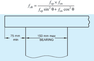
c) For bearings less than 150 mm in length located 75 mm or more from the end of a member as shown in Fig. 2, the permissible stress may be multiplied by the modification factor K7 given in Table 13.
d) No allowance need be made for the difference in intensity of the bearing stress due to bending of a beam.
e) The bearing area should be calculated as the net area after allowance for the amount of wane.
f) For bearings stress under a washer or a small plate, the same coefficient specified in Table 13 may be taken for a bearing with a length equal to the diameter of the washer or the width of the small plate.
g) When the direction of stress is at angle to the direction of the grain in any structural member, then the permissible bearing stress in that member shall be calculated by the following formula:
FIG 2. POSITION OF END BEARINGS
Table 13Modification Factor K_{7} for Bearing Stresses
Length of Bearing mm(1)
15(2)
25(3)
40(4)
50(5)
75(6)
100(7)
150 or more(8)
Modification factor, K7
1.67
1.40
1.25
1.20
1.13
1.10
1.00
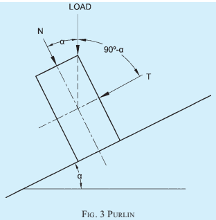
6.5.9 Purlin is a structural member, essentially a beam subjected to transverse loads and rests on the top chord of roof truss. Being under bi-axial bending, vertical loads are resolved into two components, that is, perpendicular to and parallel to roof slopes (see Fig. 3). The effect of normal and tangential components of the vertical load is worked out separately and the in fibre stress in bending, will be the algebraic sum of both.
6.5.10 Deflection
The deflection in the case of all flexural members supporting brittle materials like gypsum ceilings, slates, tiles and asbestos sheets shall not exceed 1/360 of the span. The deflection in the case of other flexural members shall not exceed 1/240 of the span and 1/150 of the freely hanging length in the case of cantilevers.
6.5.10.1 Usual formula for deflection shall apply:
δ=EIKWL3(ignoring deflection due to shear strain)
K-values = 1/3 for cantilevers with load at free end,
= 1/8 for cantilevers with uniformly distributed load,
= 1/48 for beams supported at both ends with point load at centre, and
= 5/384 for beams supported at both ends with uniformly distributed load.
6.5.10.2 In order to allow the effect of long duration loading on E, for checking deflection in case of beams and joists the effective loads shall be twice the dead load if timber is initially dry.
NOTE — The tendency of flexural members to acquire larger permanent deflections under long continued loadings has to be taken care of either by considering double the dead load in calculations of deflection or by giving a factor of safety to MOE.
6.5.10.3 Self weight of beam shall be considered in design.
6.6Columns
NOTE — The formulae given are for columns with pin end conditions and the length shall be modified suitably with other end conditions.
6.6.1 Solid Columns
Solid columns shall be classified into short, intermediate and long columns depending upon their slenderness ratio (S/d) as follows:
a) Short columns — Where S/d does not exceed 11,
b) Intermediate columns — Where S/d is between 11 and Kg, and
c) Long columns — Where S/d is greater than K8.
6.6.1.1 For short columns, the permissible compressive stress shall be calculated as follows:
PART 6 STRUCTURAL DESIGN — SECTION 3 TIMBER AND BAMBOO: 3A TIMBER
fc=fcp
6.6.1.2 For intermediate columns, the permissible compressive stress is calculated by using the following formula:
fc=fcp[1−31(K8dS)4]
6.6.1.3 For long columns, the permissible compressive stress shall be calculated by using the following formula:
fc=(S/d)20.329E
6.6.1.4 In case of solid columns of timber, S/d ratio shall not exceed 50.
6.6.1.5 The permissible load on a column of circular cross section shall not exceed that permitted for a square column of an equivalent cross sectional area, where side of square is equal to 0.886 times the diameter
6.6.1.6 For determining S/d ratio of a tapered column, such as for wooden poles, its least dimension shall be taken as the sum of the corresponding least dimensions at the small end of the column and one-third of the difference between this least dimension at the small end and the corresponding least dimension at the large end, but in no case shall the least dimension for the column be taken as more than one and a half times the least dimension at the small end. The induced stress at the small end of the tapered column shall not exceed the permissible compressive stress in the direction of grain.
6.6.2 Built-Up Columns
6.6.2.1 Box column
Box columns shall be classified into short, intermediate and long columns as follows:
a) Short columns — Where d12+d22S is less than 8;
b) Intermediate columns — Where d12+d22S is between 8 and K9 ; and
c) Long columns — Where d12+d22S is greater than K9;
6.6.2.2 For short columns, the permissible compressive stress shall be calculated as follows:
fc=qfcp
6.6.2.3 For intermediate columns, the permissible
compressive stress shall be obtained using the following formula:
fc=qfcp1−31(K9d12+d22S)4
6.6.2.4 For long columns, the permissible compressive stress shall be calculated by using the following formula:
fc=(d12+d22S)20.329UE
6.6.2.5 The following values of U and q, depending upon plank thickness (t) in 6.6.2.3 and 6.6.2.4, shall be used for width of plank not greater than 5 times the plank thickness:
t mm
U
q
25
0.80
1.00
50
0.60
1.00
6.6.3 Spaced Columns
6.6.3.1 The formulae for solid columns as specified in 6.6.1 are applicable to spaced columns with a restraint factor of 2.5 or 3, depending upon distances of end connectors in the column.
NOTE — A restrained factor of 2.5 for location of centroid group of fasteners at S/20 from end and 3 for location at S/10 to S/20 from end shall be taken.
6.6.3.2 For intermediate spaced column, the permissible compressive stress shall be:
fc=fcp[1−31(K10dS)4]
6.6.3.3 For long spaced columns, the permissible compressive stress shall be:
fc=(S/d)20.329E×2.5
6.6.3.4 For individual members of spaced columns, S/d ratio shall not exceed 80.
6.6.4 Compression members shall not be notched. When it is necessary to pass services through such a member, this shall be effected by means of a bored hole provided that the local stress is calculated and found to be within the permissible stress specified. The distance from the edge of the hole to the edge of the member shall not be less than one quarter of width of the face.
6.7 Tension Member (Ties)
The stress is axial tension parallel to grain of wood shall be calculated on the basis of net-section area which shall not exceed the safe permissible value in tension parallel to grain
fat=Area of cross - sectionMaximum force prevailing≤ft
6.8 Structural Members Subject to Bending and Axial Stresses
6.8.1 Structural members subjected both to bending and axial compression shall be designed to comply with the following:
fcfac+fbfabis not greater than 1.
6.8.2 Structural members subjected both to bending and axial tension shall be designed to comply with the following:
ftfat+fbfabis not greater than 1.
6.9 Timber Roof Truss
Trusses are framed structures in which separate straight members are so arranged and connected at their ends that members form triangles. The external loads cause direct stresses in the members. Essentially a plane structure which is very stiff in the plane of the members but very flexible in every other direction. For members subjected to reversal of stresses, design has to be for one stress and tested for the other applied at the panel points. Eccentricity of meeting members at joint may result in the increased stresses in design.