This clause primarily deals with earthquake hazard assessment and earthquake-resistant design of buildings.
All structures, like parking structures, security cabins and ancillary structures need to be designed for
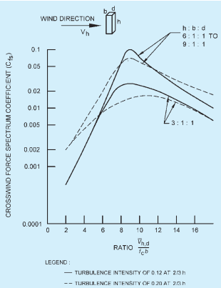
10A VALUES OF THE CROSS WIND FORCE SPECTRUM COEFFICIENT FOR SQUARE SECTION BUILDINGS
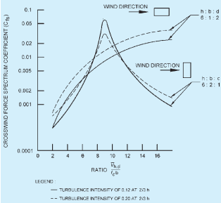
10B VALUES OF THE CROSS WIND FORCE SPECTRUM COEFFICIENT FOR 2:1 AND 1:2 RECTANGULAR SECTION BUILDINGS
FIG. 10 WIND FORCE SPECTRUM COEFFICIENT
appropriate earthquake effects as per this clause. Also, temporary elements, such as scaffolding and temporary excavations, need to be designed as per this clause. This clause does not deal with construction features relating to earthquake-resistant buildings and other
structures. For guidance on earthquake-resistant construction of buildings, reference may be made to the latest revisions of the following good practice [6 1(6)].
The provisions of this clause are applicable even to critical and special structures, like nuclear power plants and petroleum refinery plants. For such structures, additional requirements may be imposed based on special studies, such as site-specific hazard assessment. In such cases, the earthquake effects specified by this clause shall be taken as at least the minimum.
For the purpose of this clause the symbols given at Annex G are applicable.
5.1Terminology
For the purpose of this clause, definitions given below shall apply to all structures, in general. For definition of terms pertaining to soil mechanics and soil dynamics, reference may be made to Part 6 ‘Structural Design, Section 2 Soils and Foundations’ of the Code; and for definition of terms pertaining to ‘Loads’, 3.2 and 4.3 may be referred.
5.1.1 Closely-Spaced Modes — Closely-spaced modes of a structure are those of the natural modes of oscillation of a structure, whose natural frequencies differ from each other by 10 percent or less of the lower frequency.
5.1.2 Critical Damping — The damping beyond which the free vibration motion will not be oscillatory.
5.1.3 Damping — The effect of internal friction, inelasticity of materials, slipping, sliding, etc, in reducing the amplitude of oscillation; it is expressed as a fraction of critical damping (see 5.1.2).
5.1.4 Design Acceleration Spectrum — Design acceleration spectrum refers to an average smoothened graph of maximum acceleration as a function of natural frequency or natural period of oscillation for a specified damping ratio for the expected earthquake excitations at the base of a single degree of freedom system.
5.1.5 Design Horizontal Acceleration Coefficient (Ah) — It is a horizontal acceleration coefficient that shall be used for design of structures.
5.1.6 Design Horizontal Force — It is the horizontal seismic force prescribed by this Section that shall be used to design a structure.
5.1.7 Ductility — It is the capacity of a structure (or its members) to undergo large inelastic deformations without significant loss of strength or stiffness.
5.1.8 Epicentre — It is the geographical point on the
PART 6 STRUCTURAL DESIGN — SECTION 1 LOADS, FORCES AND EFFECTS
surface of earth vertically above the point of origin of the earthquake.
5.1.9 Floor Response Spectrum — It is the response spectrum (for a chosen material damping value) of the time history of the shaking generated at a floor of a structure, when the structure is subjected to a given earthquake ground motion at its base.
5.1.10 Importance Factor (I) — It is a factor used to estimate design seismic force depending on the functional use of the structure, characterized by hazardous consequences of its failure, post-earthquake functional needs, historical value, or economic importance.
5.1.11 Intensity of Earthquake — It is the measure of the strength of ground shaking manifested at a place during the earthquake, and is indicated by a roman capital numeral on the MSK scale of seismic intensity (see Annex H).
5.1.12 Liquefaction — It is a state primarily in saturated cohesionless soils wherein the effective shear strength is reduced to negligible value for all engineering purposes, when the pore pressure approaches the total confining pressure during earthquake shaking. In this condition, the soil tends to behave like a fluid mass (see Annex J).
5.1.13 Lithological Features — Features that reflect the nature of the geological formation of the earth's crust above bed rock characterized on the basis of structure, mineralogical composition and grain size.
5.1.14 Modal Mass ( Mk ) in Mode (k) of a Structure — It is a part of the total seismic mass of the structure that is effective in natural mode k of oscillation during horizontal or vertical ground motion.
5.1.15 Modal Participation Factor ( Pk ) in Mode (k) of a Structure — The amount by which natural mode k contributes to overall oscillation of the structure during horizontal or vertical earthquake ground motion. Since the amplitudes of mode shapes can be scaled arbitrarily, the value of this factor depends on the scaling used for defining mode shapes.
5.1.16 Modes of Oscillation — See 5.1.19.
5.1.17 Mode Shape Coefficient ( ϕik ) — It is the spatial deformation pattern of oscillation along degree of freedom i, when the structure is oscillating in its natural mode k. A structure with N degrees of freedom possesses N natural periods and N associated natural mode shapes. These natural mode shapes are together presented in the form of a mode shape matrix [ ϕ ], in which each column represents one natural mode shape. The element ϕik is called the mode shape coefficient
associated with degree of freedom i, when the structure is oscillating in mode k.
5.1.18 Natural Period ( Tk ) in Mode (k) of Oscillation — The time taken (in second) by the structure to complete one cycle of oscillation in its natural mode k of oscillation.
5.1.18.1 Fundamental lateral translational natural period (T1) — It is the longest time taken (in second) by the structure to complete one cycle of oscillation in its lateral translational mode of oscillation in the considered direction of earthquake shaking. This mode of oscillation is called the fundamental lateral translational natural mode of oscillation. A three-dimensional model of a structure will have one such fundamental lateral translational mode of oscillation along each of the two orthogonal plan directions.
5.1.19 Normal Mode of Oscillation — The mode of oscillation in which there are special undamped free oscillations in which all points on the structure oscillate harmonically at the same frequency (or period), such that all these points reach their individual maximum responses simultaneously.
5.1.20 Peak Ground Acceleration — It is the maximum acceleration of the ground in a given direction of ground shaking. Here, the acceleration refers to that of the horizontal motion, unless specified otherwise.
5.1.21 Response Reduction Factor(R) — It is the factor by which the base shear induced in a structure, if it were to remain elastic, is reduced to obtain the design base shear. It depends on the perceived seismic damage performance of the structure, characterized by ductile or brittle deformations, redundancy in the structure, or overstrength inherent in the design process.
5.1.22 Response Spectrum — It is the representation of maximum responses of a spectrum of idealized single degree freedom systems of different natural periods but having the same damping, under the action of the same earthquake ground motion at their bases. The response referred to here can be maximum absolute acceleration, maximum relative velocity, or maximum relative displacement.
5.1.23 Response Acceleration Coefficient of a Structure (Sa/g) — It is a factor denoting the normalized design acceleration spectrum value to be considered for the design of structures subjected to earthquake ground shaking; this value depends on the natural period of oscillation of the structure and damping to be considered in the design of the structure.
5.1.24 Seismic Mass of a Floor — It is the seismic
weight of the floor divided by acceleration due to gravity.
5.1.25 Seismic Mass of a Structure — It is the seismic weight of a structure divided by acceleration due to gravity.
5.1.26 Seismic Weight of a Floor (W) — It is the sum of dead load of the floor, appropriate contributions of weights of columns, walls and any other permanent elements from the storeys above and below, finishes and services, and appropriate amounts of specified imposed load on the floor.
5.1.27 Seismic Weight of a Structure (W) — It is the sum of seismic weights of all floors.
5.1.28 Seismic Zone Factor (Z) — It is the value of peak ground acceleration considered by this Section for the design of structures located in each seismic zone.
5.1.29 Time History Analysis — It is an analysis of the dynamic response of the structure at each instant of time, when its base is subjected to a specific ground motion time history.
5.2Special Terminology for Buildings
5.2.1 The definitions given below shall apply for the purpose of earthquake resistant design of buildings, as enumerated in this Section.
5.2.2 Base — It is the level at which inertia forces generated in the building are considered to be transferred to the ground through the foundation. For buildings with basements, it is considered at the bottommost basement level. For buildings resting on,
a) pile foundations, it is considered to be at the top of pile cap;
b) raft, it is considered to be at the top of raft; and
c) footings, it is considered to be at the top of the footing.
For buildings with combined types of foundation, the base is considered as the bottom-most level of the bases of the constituent individual foundations as per definitions above.
5.2.3 Base Dimension (d) — It is the dimension (in metre) of the base of the building along a direction of shaking.
5.2.4 Centre of Mass (CM) — The point in the floor of a building through which the resultant of the inertia force of the floor is considered to act during earthquake shaking. Unless otherwise stated, the inertia force considered is that associated with the horizontal shaking of the building.
5.2.5 Centre of Resistance (CR)
5.2.5.1 For single storey buildings — It is the point on
the roof of a building through which when the resultant internal resistance acts, the building undergoes,
a) pure translation in the horizontal direction; and
b) no twist about vertical axis passing through the CR.
5.2.5.2 For multi-storey buildings — It is the set of points on the horizontal floors of a multi-storey building through which, when the resultant incremental internal resistances across those floors act, all floors of the building undergo,
a) pure translation in the horizontal direction; and
b) no twist about vertical axis passing through the CR.
5.2.6 Eccentricity
5.2.6.1 Design eccentricity ( edi ) — It is the value of eccentricity to be used for floor i in calculations of design torsion effects.
5.2.6.2 Static eccentricity (esi) — It is the distance between centre of mass (CM) and centre of resistance (CR) of floor i.
5.2.7 Design Seismic Base Shear ( VB ) — It is the horizontal lateral force in the considered direction of earthquake shaking that the structure shall be designed for.
5.2.8 Diaphragm — It is a horizontal or nearly horizontal structural system (for example, reinforced concrete floors and horizontal bracing systems), which transmits lateral forces to vertical elements connected to it.
5.2.9 Height of Floor ( hi ) — It is the difference in vertical elevations (in metre) of the base of the building and top of floor i of the building.
5.2.10 Height of Building (h) — It is the height of building (in metre) from its base to top of roof level,
a) excluding the height of basement storeys, if basement walls are connected with the ground floor slab or basement walls are fitted between the building columns, but
b) including the height of basement storeys, if basement walls are not connected with the ground floor slab and basement walls are not fitted between the building columns.
In step-back buildings, it shall be taken as the average of heights of all steps from the base, weighted with their corresponding floor areas. And, in buildings founded on hill slopes, it shall be taken as the height of the roof from the top of the highest footing level or pile cap level.
PART 6 STRUCTURAL DESIGN — SECTION 1 LOADS, FORCES AND EFFECTS
5.2.11 Horizontal Bracing System — It is a horizontal truss system that serves the same function as a diaphragm.
5.2.12 Joints — These are portions of columns that are common to beams/braces and columns, which frame into columns.
5.2.13 Lateral Force Resisting System — It is part of the structural system, and consists of all structural members that resist lateral inertia forces induced in the building during earthquake shaking.
5.2.14 Moment-Resisting Frame — It is an assembly of beams and columns that resist induced and externally applied forces primarily by flexure.
5.2.14.1 Ordinary moment-resisting frame (OMRF)—It is a moment-resisting frame designed and detailed as per relevant good practices [6-1(7)], but not meeting special detailing requirements for ductile behaviour as per good practices [6-1(8)] or [6-1(9)], as applicable.
5.2.14.2 Special moment-resisting frame (SMRF) — It is a moment-resisting frame designed and detailed as per relevant good practices [6-1(7)], and meeting special detailing requirements for ductile behaviour as per good practices [6-1(8)] or [6-1(9)], as applicable.
5.2.15 Number of Storeys (n) — It is the number of levels of a building above the base at which mass is present in substantive amounts. This,
a) excludes the basement storeys, where basement walls are connected with the ground floor deck or fitted between the building columns; and
b) includes the basement storeys, when they are not so connected.
5.2.16 Core Structural Walls, Perimeter Columns, Outriggers and Belt Truss System — It is a structural system comprising a core of structural walls and perimeter columns, resisting the vertical and lateral loads, with
a) the core structural walls connected to select perimeter column element(s) (often termed outrigged columns) by deep beam elements, known as outriggers, at discrete locations along the height of the building; and
b) the outrigged columns connected by deep beam elements (often known as belt truss), typically at the same level as the outrigger elements.
A structure with this structural system has enhanced lateral stiffness, wherein core structural walls and perimeter columns are mobilized to act with each other
through the outriggers, and the perimeter columns themselves through the belt truss. The global lateral stiffness is sensitive to: flexural stiffness of the core element, the flexural stiffness of the outrigger element(s), the axial stiffness of the outrigged column(s), and the flexural stiffness of the outrigger elements connecting the core structural walls to the perimeter columns.
5.2.17 Principal Plan Axes — These are two mutually perpendicular horizontal directions in plan of a building along which the geometry of the building is oriented.
5.2.18 P- Δ Effect — It is the secondary effect on shear forces and bending moments of lateral force resisting elements generated under the action of the vertical loads, interacting with the lateral displacement of building resulting from seismic effects.
5.2.19 RC Structural Wall — It is a wall designed to resist lateral forces acting in its own plane.
5.2.19.1 Ordinary RC structural wall — It is a reinforced concrete (RC) structural wall designed and detailed as per good practice [6-1(10)], but not meeting special detailing requirements for ductile behaviour as per good practice [6-1(8)].
5.2.19.2 Special RC structural wall — It is a RC structural wall designed and detailed in accordance with and meeting special detailing requirements for ductile behaviour, as per good practice [6-1(8)].
5.2.20 Storey — It is the space between two adjacent floors.
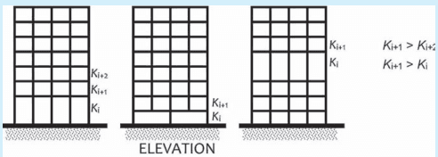
5.2.20.1 Soft storey — It is one in which the lateral stiffness is less than that in the storey above. The storey lateral stiffness is the total stiffness of all seismic force resisting elements resisting lateral earthquake shaking effects in the considered direction.
5.2.20.2 Weak storey — It is one in which the storey lateral strength [cumulative design shear strength of all structural members other than that of unreinforced masonry (URM) infills] is less than that in the storey above. The storey lateral strength is the total strength of all seismic force resisting elements sharing the lateral storey shear in the considered direction.
5.2.21 Storey Drift — It is the relative displacement between the floors above and/or below the storey under consideration.
5.2.22 Storey Shear ( Vi ) — It is the sum of design lateral forces at all levels above the storey i under consideration.
5.2.23 Storey Lateral Shear Strength (Si) — It is the total lateral strength of all lateral force resisting
elements in the storey considered in a principal plan direction of the building.
5.2.24 Storey Lateral Translational Stiffness ( Ki ) — It is the total lateral translational stiffness of all lateral force resisting elements in the storey considered in a principal plan direction of the building.
5.2.25 RC Structural Wall Plan Density ( ρsw ) — It is the ratio of the cross-sectional area at the plinth level of RC structural walls resisting the lateral load and the plinth of the building, expressed as a percentage.
5.3General Principles and Design Criteria
5.3.1 General Principles
5.3.1.1 Ground motion
The characteristics (intensity, duration, frequency content, etc) of seismic ground vibrations expected at any site depend on magnitude of earthquake, its focal depth, epicentral distance, characteristics of the path through which the seismic waves travel, and soil strata on which the structure is founded. The random earthquake ground motions, which cause the structure to oscillate, can be resolved in any three mutually perpendicular directions. The predominant direction of ground vibration is usually horizontal.
Effects of earthquake-induced vertical shaking can be significant for overall stability analysis of structures, especially in structures (a) with large spans, and (b) those in which stability is a criterion for design. Reduction in gravity force due to vertical ground motions can be detrimental particularly in prestressed horizontal members, cantilevered members and gravity structures. Hence, special attention shall be paid to effects of vertical ground motion on prestressed or cantilevered beams, girders and slabs.
5.3.1.2 The response of a structure to ground vibrations depends on (a) type of foundation; (b) materials, form, size and mode of construction of structures; and (c) duration and characteristics of ground motion. This Section specifies design forces for structures founded on rocks or soils, which do not settle, liquefy or slide due to loss of strength during earthquake ground vibrations.
5.3.1.3 Actual forces that appear on structures during earthquakes are much higher than the design forces specified in the Section. Ductility arising from inelastic material behaviour with appropriate design and detailing, and overstrength resulting from the additional reserve strength in structures over and above the design strength are relied upon for the deficit in actual and design lateral loads. In other words,
earthquake resistant design as per this Section relies on inelastic behaviour of structures. But, the maximum ductility that can be realized in structures is limited. Therefore, structures shall be designed for at least the minimum design lateral force specified in this Section.
5.3.1.4 Members and connections of reinforced and prestressed concrete structures shall be designed (as per good practices [6-1(11)] such that premature failure does not occur due to shear or bond. Some provisions for appropriate ductile detailing of RC members are given in good practice [6-1(8)]. Members and their connections of steel structures should be so proportioned that high ductility is obtained in the structure, avoiding premature failure due to elastic or inelastic buckling of any type. Some provisions for appropriate ductile detailing of steel members are given in good practice [6-1(9)].
5.3.1.5 The soil-structure interaction refers to effects of the flexibility of supporting soil-foundation system on the response of structure. Soil-structure interaction may not be considered in the seismic analysis of structures supported on rock or rock-like material at shallow depth.
5.3.1.6 Equipment and other systems, which are supported at various floor levels of a structure, will be subjected to different motions at their support points. In such cases, it may be necessary to obtain floor response spectra for design of equipment and its supports. For details, reference may be made to good practice [6-1(12)].
5.3.1.7 Additions to existing structures
Additions shall be made to existing structures only as follows:
a) An addition that is structurally independent from an existing structure shall be designed and constructed in accordance with the seismic requirements for new structures.
b) An addition that is structurally connected to an existing structure shall be designed and constructed such that the entire structure conforms to the seismic force resistance requirements for new structures, unless the following three conditions are complied with:
Addition shall comply with the requirements for new structures,
Addition shall not increase the seismic forces in any structural element of the existing structures by more than 5 percent, unless the capacity of the element subject to the increased force is
PART 6 STRUCTURAL DESIGN — SECTION 1 LOADS, FORCES AND EFFECTS
still in compliance with this Section, and
Addition shall not decrease the seismic resistance of any structural element of the existing structure unless reduced resistance is equal to or greater than that required for new structures.
5.3.1.8 Change in occupancy
When a change of occupancy results in a structure being reclassified to a higher importance factor (I), the structure shall conform to seismic requirements laid down for new structures with the higher importance factor.
5.3.3Load Combinations and Increase in Permissible Stresses
5.3.3.1 Load combinations
The load combinations shall be considered as specified in respective standards due to all load effects mentioned therein. In addition, those specified in this standard shall be applicable, which include earthquake effects.
5.3.3.1.1 Even when load combinations that do not contain earthquake effects, indicate larger demands than combinations including them, the provisions shall be adopted related to design, ductile detailing and construction relevant for earthquake conditions, which are given in this Section, good practice [6-1(8)] and good practice [6-1(9)].
5.3.3.2 Design horizontal earthquake load
5.3.3.2.1 When lateral load resisting elements are oriented along two mutually orthogonal horizontal directions, structure shall be designed for effects due to full design earthquake load in one horizontal direction at a time, and not in both directions simultaneously.
5.3.3.2.2 When lateral load resisting elements are not oriented along mutually orthogonal horizontal directions [as per 5.4.1 and Sl No. (v) of Table 44], structure shall be designed for the simultaneous effects due to full design earthquake load in one horizontal direction plus 30 percent of design earthquake load along the other horizontal direction. Thus, structure should be designed for the following sets of combinations of earthquake effects:
a)b)±ELX±0.3ELY,and±0.3ELX±ELY,
where X and Y are two orthogonal horizontal plan directions. Thus, EL in the load combinations shall be replaced by (ELX±0.3ELY) or (ELY±0.3ELX) . Hence, the sets of load combinations to be considered shall be as given below:
1.2[DL+IL±(ELX±0.3ELY)] and
1.2[DL+IL±(ELY±0.3ELX)];
1.5[DL±(ELX±0.3ELY)] and
1.5[DL±(ELY±0.3ELX)];and
0.9DL±1.5(ELX±0.3ELY) and
0.9DL±1.5(ELY±0.3ELX).
5.3.3.3 Design vertical earthquake effects
5.3.3.3.1 Effects due to vertical earthquake shaking shall be considered when any of the following conditions apply:
a) Structure is located in Seismic Zone IV or V;
b) Structure has vertical or plan irregularities;
c) Structure is rested on soft soil;
d) Bridges;
e) Structure has long spans; or
f) Structure has large horizontal overhangs of structural members or sub-systems.
5.3.3.3.2 When effects due to vertical earthquake shaking are to be considered, the design vertical force shall be calculated for vertical ground motion as detailed in 5.3.4.6.
5.3.3.3.3 Where both horizontal and vertical seismic
forces are taken into account, load combination specified in 5.3.3.4 shall be considered.
5.3.3.4 Combinations to account for three directional earthquake ground shaking
5.3.3.4.1 When responses from the three earthquake components are to be considered, the responses due to each component may be combined using the assumption that when the maximum response from one component occurs, the responses from the other two components are 30 percent each of their maximum. All possible combinations of three components ( ELX , ELY and ELZ ) including variations in sign (plus or minus) shall be considered. Thus, the structure should be designed for the following sets of combinations of earthquake load effects:
where X and Y are orthogonal plan directions and Z vertical direction. Thus, EL in the above referred load combinations shall be replaced by (ELX±0.3ELY±0.3ELZ), (ELY±0.3ELZ±0.3ELX) or (ELZ±0.3ELX±0.3ELY). This implies that the sets of load combinations involving earthquake effects to be considered shall be as given below:
5.3.3.4.2 As an alternative to the procedure in 5.3.3.4.1, the net response (EL) due to the combined effect of the three components can be obtained by:
EL=(ELX)2+(ELY)2+(ELZ)2
Caution may be exercised on loss of sign especially of the axial force, shear force and bending moment quantities, when this procedure is used; it can lead to grossly uneconomical design of structures.
5.3.3.4.3 Procedure for combining shaking effects given by 5.3.3.4.1 and 5.3.3.4.2 apply to the same response quantity (say, bending moment in a column about its major axis, or storey shear force in a frame) due to different components of the ground motion.
5.3.3.4.4 When components corresponding to only two ground motion components (say one horizontal and one vertical, or only two horizontal) are combined, the equations in 5.3.3.4.1 and 5.3.3.4.2 should be modified by deleting the term representing the response due to the component of motion not being considered.
5.3.3.5 Increase in net pressure on soils in design of foundations
5.3.3.5.1 In the design of foundations, unfactored loads shall be combined in line with good practices [6-1(14)], while assessing the bearing pressure in soils.
5.3.3.5.2 When earthquake forces are included, net bearing pressure in soils can be increased as per Table 40, depending on type of foundation and type of soil. For determining the type of soil for this purpose, soils shall be classified in four types as given in Table 41. In soft soils, no increase shall be applied in bearing pressure, because settlements cannot be restricted by increasing bearing pressure.
5.3.3.5.3 In soil deposits consisting of submerged loose sands and soils falling under classification SP with corrected standard penetration test values N, less than 15 in Seismic Zones III, IV and V, and less than 10 in Seismic Zone II, the shaking caused by earthquake ground motion may cause liquefaction or excessive total and differential settlements. Such sites should be avoided preferably for locating new structures, and should be avoided for locating structures of important projects. Otherwise, settlements need to be investigated, and appropriate methods adopted of compaction or stabilization to achieve N values indicated in Note 4 of Table 40. Alternatively, deep pile foundations may be adopted and anchored at depths well below the underlying soil layers, which are likely to liquefy or undergo excessive settlements.
Also, marine clay layers and other sensitive clay layers are known to liquefy, undergo excessive settlements or even collapse, owing to low shear strength of the said soil; such soils will need special treatment according to site condition (see Table 41).
A simplified method is given in Annex J, for evaluation of liquefaction potential.
5.3.4Design Acceleration Spectrum
5.3.4.1 For the purpose of determining design seismic force, the country is classified into four seismic zones as shown in Fig. 11.
PART 6 STRUCTURAL DESIGN — SECTION 1 LOADS, FORCES AND EFFECTS
Table 40Percentage Increase in Net Bearing Pressure and Skin Friction of Soils (Clause 5.3.3.5.2)
Sl No.
Soil Type
Percentage Increase Allowable
(1)
(2)
(3)
i)
Type A: Rock or hard soils
50
ii)
Type B: Medium or stiff soils
25
iii)
Type C: Soft soils
0
NOTES
1 The net bearing pressure shall be determined in accordance with good practice [6-1(15)] or accepted standards [6-1(16)]
2 Only corrected values of N shall be used.
3 If any increase in net bearing pressure has already been permitted for forces other than seismic forces, the total increase in allowable bearing pressure, when seismic force is also included, shall not exceed the limits specified above.
4 The desirable minimum corrected field values of N shall be as specified below:
Seismic Zone
Depth (m) belowGround Level
N Values
Remarks
III, IV and V
≤5≥10
1525
For values of depths between 5 m and 10 m, linear interpolation is recommended
II
≤5≥10
1020
If soils of lower N values are encountered than those specified in the table above, then suitable ground improvement techniques shall be adopted to achieve these values. Alternately, deep pile foundations should be used, which are anchored in stronger strata, underlying the soil layers that do not meet the requirement.
5 Piles should be designed for lateral loads neglecting lateral resistance of those soil layers (if any), which are liable to liquefy.
6 Accepted standard [6-1(17)] may be referred for soil notation, and corrected N values shall be determined by applying correction
factor CN for effective overburden pressure σvo′ using relation N=CNN1, where CN=Ps/σvo′≤1.7, Ps is the atmospheric pressure, and N1 is the uncorrected SPT value for soil.
7 While using this table, the value of N to be considered shall be determined as below:
a) Isolated footings — Weighted average of N of soil layers from depth of founding, to depth of founding plus twice the breadth of footing;
b) Raft foundations — Weighted average of N of soil layers from deptb of founding, to depth of founding plus twice the breadth of raft;
c) Pile foundation — Weighted average of N of soil layers from depth of bottom tip of pile, to depth of bottom tip of pile plus twice the diameter of pile;
d) Group pile foundation — Weighted average of N of soil layers from depth of bottom tip of pile group, to depth of bottom tip of pile group plus twice the width of pile group; and
e) Well foundation — Weighted average of N of soil layers from depth of bottom tip of well, to depth of bottom tip of well plus twice the width of well.
Table 41Classification of Types of Soils for Determining Percentage Increase in Net Bearing Pressure and Skin Friction (Clause 5.3.3.5.2)
Sl No.(1)
Soil Type(2)
Remarks(3)
i)
Type ARock or hard soils
Well graded gravel (GW) or well graded sand (SW) both with less than 5 percent passing 75 μm sieve (Fines)Well graded gravel - sand mixtures with or without fines (GW-SW)Poorly-graded sand (SP) or Clayey sand (SC), all having N above 30 stiff to hard clays having N above 30, where N is corrected standard penetration test value
ii)
Type BMedium or stiff soils
Poorly graded sands or poorly graded sands with gravel (SP) with little or no fines having N between 10 and 30Stiff to medium stiff fine-grained soils, like silts of low compressibility (ML) or clays of low compressibility (CL) baving N between 10 and 30
iii)
Type CSoft soils
All soft soils other than SP with N<10. The various possible soils are:a) Silts of intermediate compressibility (MI);b) Silts of high compressibility (MH);c) Clays of intermediate compressibility (CI);d) Clays of high compressibility (CH);e) Silts and clays of intermediate to high compressibility (MI-MH or CI-CH);f) Silt with clay of intermediate compressibility (MI-CI); andg) Silt with clay of high compressibility (MH-CH).
iv)
Type DUnstable, collapsible, liquefiable soils
Requires site-specific study and special treatment according to site condition (see 5.3.3.5.3)
Based upon Survey of India Political map printed in 2002.
The territorial waters of India extend into the sea to a distance of twelve nautical miles measured from the appropriate baseline.
The interstate boundaries between Arunachal Pradesh, Assam and Meghalaya shown on this map are as interpreted from the North-Eastern Areas (Reorganization) Act, 1971, but have yet to be verified.
The state boundaries between Uttarakhand & Uttar Pradesh, Bihar & Jharkhand, and Chhattisgarh & Madhya Pradesh have not been verified by the Governments concerned.
The administrative headquarters of Chandigarh, Haryana and Punjab are at Chandigarh.
The external boundaries and coastlines of India agree with the Record/Master Copy certified by Survey of India.
The responsibility for the correctness of internal details rests with the publisher.
NOTE – Towns falling at the boundary of zones demarcation line between two zones shall be considered in higher zone.
FIG. 11 SEISMIC ZONES OF INDIA
The image contains no text or content to process. It is a blank white background with no visible content, text, or symbols. Therefore, the correct OCR output is an empty string.
5.3.4.2 The design horizontal seismic coefficient Ah for a structure shall be determined by:
Ah=(IR)(2Z)(gSa)
where
Z= seismic zone factor given in Table 42. Zone factor for some important towns are given at Annex K;
I= importance factor given in good practice [6-1(18)] for the corresponding structures; when not specified, the minimum values of I shall be,
a) 1.5 for critical and lifeline structures;
b) 1.2 for business continuity structures; and
c) 1.0 for the rest.
R= response reduction factor given in good practice [6-1(18)] for the corresponding structures; and
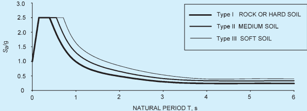
(gSa)= design acceleration coefficient for different soil types, normalized with peak ground acceleration,
corresponding to natural period T of structure (considering soil-structure interaction, if required). It shall be as given in good practice [6-1(18)] for the corresponding structures; when not specified, it shall be taken as that corresponding to 5 percent damping, given by expressions below:
a) For use in equivalent static method (see Fig. 12A):
gSa=⎩⎨⎧For rocky or hard soil sitesFor medium stiff soil sitesFor soft soil sites⎩⎨⎧2.5T10.250<T<0.40s0.40s<T<4.00sT>0.400s⎩⎨⎧2.5T1.360.340<T<0.55s0.55s<T<4.00sT>0.400s⎩⎨⎧2.5T1.670.420<T<0.67s0.67s<T<4.00sT>0.400s
b) For use in response spectrum method (see Fig. 12B):
5.3.4.2.1 For determining the correct spectrum to be used in the estimate of Sa/g, the type of soil on which the structure is placed shall be identified by the classification given in Table 43, as:
a) Soil type I — Rock or hard soils;
b) Soil type II — Medium or stiff soils; and
c) Soil type III — Soft soils.
In Table 43, the value of N to be used shall be the weighted average of N of soil layers from the existing ground level, to 30m below the existing ground level; here, the N values of individual layers shall be the corrected values.
5.3.4.3 Effects of design earthquake loads applied on structures can be considered in two ways, namely:
a) Equivalent static method, and
b) Dynamic analysis method.
In turn, dynamic analysis can be performed in three ways, namely:
Response spectrum method,
Modal time history method, and
Time history method.
In this Section, equivalent static method, response spectrum method and time history method are adopted. Equivalent static method may be used for analysis of regular structures with approximate natural period Ta less than 0.4 s.
5.3.4.3.1 For structural analysis, the moment of inertia shall be taken as:
a) In RC and masonry structures: 70 percent of Igross of columns, and 35 percent of Igross of beams; and
b) In steel structures: Igross of both beams and columns.
5.3.4.4 Where a number of modes are to be considered in response spectrum method, Ah as defined in 5.3.4.2 for each mode k shall be determined using natural period Tk of oscillation of that mode.
Table 43Classification of Types of Soils for Determining the Spectrum to be Used to Estimate Design Earthquake Force (Clause 5.3.4.2.1)
Sl No.
Soil Type
Remarks
(1)
(2)
(3)
i)
IRock or Hard soils
a) Well graded gravel (GW) or well graded sand (SW) both with less than 5 percent passing 75 μm sieve (Fines)b) Well graded gravel-sand mixtures with or without fines (GW-SW)c) Poorly graded sand (SP) or clayey sand (SC), all having N above 30d) Stiff to hard clays having N above 30, where N is standard penetration test value
ii)
IIMedium or Stiff soils
a) Poorly graded sands or poorly graded sands with gravel (SP) with little or no fines having N between 10 and 30b) Stiff to medium stiff fine-grained soils, like silts of low compressibility (ML) or clays of low compressibility (CL) having N between 10 and 30
iii)
IIISoft soils
All soft soils other than SP with N<10.The various possible soils are:a) Silts of intermediate compressibility (MI)b) Silts of high compressibility (MH);c) Clays of intermediate compressibility (CI)d) Clays of high compressibility (CH);e) Silts and clays of intermediate to high compressibility (MI-MH or CI-CH)d) Silt with clay of intermediate compressibility (MI-CI)g) Silt with clay of high compressibility (MH-CH).
5.3.4.5 For underground structures and buildings whose base is located at depths of 30m or more, Ah at the base shall be taken as half the value obtained from 5.3.4.2. This reduced value shall be used only for estimating inertia effects due to masses at the corresponding levels below the ground; the inertia effects for the above ground portion of the building shall be estimated based on the unreduced value of Ah. For estimating inertia effects due to masses of structures and foundations placed between the ground level and 30m depth, the design horizontal acceleration spectrum value shall be linearly interpolated between Ah and 0.5Ah where Ah is as specified in 5.3.4.2.
5.3.4.6 The design seismic acceleration spectral value Av for vertical motions shall be taken as:
Av=⎩⎨⎧(IR)(32×2Z)(2.5)(IR)(32×2Z)(2.5)(IR)(32×2Z)(gSa)(IR)(32×2Z)(gSa)For buildings governed by IS 1893 (Part 1)For liquid retaining tanks governed by IS 1893 (Part 2)For bridges governed by IS 1893 (Part 3)For industrial structures governed by IS 1893 (Part 4)
The value of Sa/g shall be based on natural period T corresponding to the first vertical mode of oscillation, using 5.3.4.2.
5.3.4.7 When design acceleration spectrum is developed specific to a project site, the same may be used for design of structures of the project. In such cases, effects of the site-specific spectrum shall not be less than those arising out of the design spectrum specified in this Section.
5.4Buildings
The four main desirable attributes of an earthquake resistant building are:
a) Robust structural configuration,
b) At least a minimum elastic lateral stiffness,
c) At least a minimum lateral strength, and
d) Adequate ductility.
5.4.1 Regular and Irregular Configurations
Buildings with simple regular geometry and uniformly distributed mass and stiffness in plan and in elevation, suffer much less damage, than buildings with irregular configurations. All efforts shall be made to eliminate irregularities by modifying architectural planning and structural configurations. A building shall be considered to be irregular for the purpose of this Section, even if any one of the conditions given in Tables 44 and 45 is applicable. Limits on irregularities for Seismic Zones III, IV and V and special requirements are laid out in Tables 44 and 45.
PART 6 STRUCTURAL DESIGN — SECTION 1 LOADS, FORCES AND EFFECTS
Table 44 Definitions of Irregular Buildings —Plan Irregularities (see Fig. 13)(Clause 5.4.1)
SI No.(1)
Type of Plan Irregularity(2)
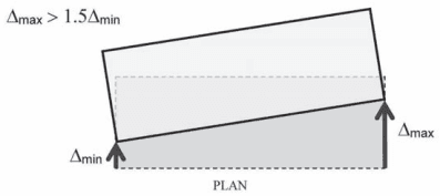
i) Torsional IrregularityUsually, a well-proportioned building does not twist about its vertical axis, whena) the stiffness distribution of the vertical elements resisting lateral loads is balanced in plan according to the distribution of mass in plan (at each storey level); andb) the floor slabs are stiff in their own plane (this happens when its plan aspect ratio is less than 3)A building is said to be torsionally irregular, when,1) the maximum horizontal displacement of any floor in the direction of the lateral force at one end of the floor is more than 1.5 times its minimum horizontal displacement at the far end of the same floor in that direction; and2) the natural period corresponding to the fundamental torsional mode of oscillation is more than those of the first two translational modes of oscillation along each principal plan directionsIn torsionally irregular buildings, when the ratio of maximum horizontal displacement at one end and the minimum horizontal displacement at the other end is,i) in the range 1.5 - 2.0, (a) the building configuration shall be revised to ensure that the natural period of the fundamental torsional mode of oscillation shall be smaller than those of the first two translational modes along each of the principal plan directions, and then (b) three dimensional dynamic analysis method shall be adopted; andii) more than 2.0, the building configuration shall be revised
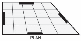
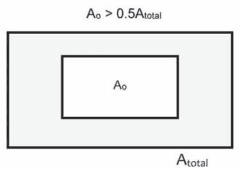
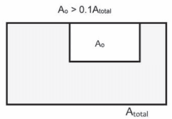
ii) Re-entrant CornersA building is said to have a re-entrant corner in any plan direction, when its structural configuration in plan has a projection of size greater than 15 percent of its overall plan dimension in that directionIn buildings with re-entrant corners, three-dimensional dynamic analysis method shall be adoptediii) Floor Slabs having Excessive Cut-Outs or OpeningsOpenings in slabs result in flexible diaphragm behaviour, and hence the lateral shear force is not shared by the frames and/or vertical members in proportion to their lateral translational stiffness. The problem is particularly accentuated when the opening is close to the edge of the slab. A building is said to have discontinuity in their in-plane stiffness, when floor slabs have cut-outs or openings of area more than 50 percent of the full area of the floor slabIn buildings with discontinuity in their in-plane stiffness, if the area of the geometric cut-out is,a) less than or equal to 50 percent, the floor slab shall be taken as rigid or flexible depending on the location of and size of openings; andb) more than 50 percent, the floor slab shall be taken as flexibleiv) Out-of-Plane Offsets in Vertical ElementsOut-of-plane offsets in vertical elements resisting lateral loads cause discontinuities and detours in the load path, which is
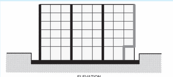
Table 44 — (Concluded)known to be detrimental to the earthquake safety of the building. A building is said to have out-of-plane offset in vertical elements, when structural walls or frames are moved out of plane in any storey along the height of the buildingIn a building with out-of-plane offsets in vertical elements,a) specialist literature shall be referred for design of such a building, if the building is located in Seismic Zone II; andb) the following two conditions shall be satisfied, if the building is located in Seismic Zones III, IV and V:1) Lateral drift shall be less than 0.2 percent in the storey having the offset and in the storeys below; and2) Specialist literature shall be referred for removing the irregularity arising due to out-of-plane offsets in vertical elements.v) Non-Parallel Lateral Force SystemBuildings undergo complex earthquake behaviour and hence damage, when they do not have lateral force resisting systems oriented along two plan directions that are orthogonal to each other. A building is said to have non-parallel system when the vertically oriented structural systems resisting lateral forces are not oriented along the two principal orthogonal axes in planBuildings with non-parallel lateral force resisting system shall be analysed for load combinations mentioned in 5.3.3.2.2 or 5.3.3.4.1.
Table 45 Definition of Irregular Buildings —Vertical Irregularities (see Fig. 14)(Clause 5.4.1)
SI No.(1)
Type of Plan Irregularity(2)
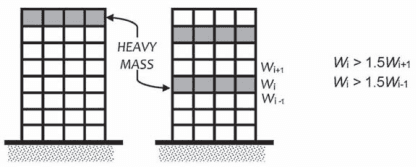
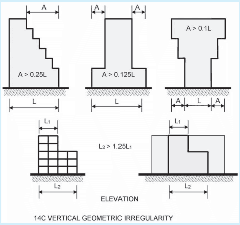
i) Stiffness Irregularity (Soft Storey)A soft storey is a storey whose lateral stiffness is less than that of the storey above.The structural plan density (SPD) shall be estimated when unreinforced masonry infills are used. When SPD of masonry infills exceeds 20 percent, the effect of URM infills shall be considered by explicitly modelling the same in structural analysis (as per 5.4.9). The design forces for RC members shall be larger of that obtained from analysis of:a) Bare frame, andb) Frames with URM infills,using 3D modelling of the structure. In buildings designed considering URM infills, the inter-storey drift shall be limited to 0.2 percent in the storey with stiffening and also in all storeys below.ii) Mass IrregularityMass irregularity shall be considered to exist, when the seismic weight (as per 5.4.7) of any floor is more than 150 percent of that of the floors below.In buildings with mass irregularity and located in Seismic Zones III, IV and V, the earthquake effects shall be estimated by Dynamic Analysis Method (as per 5.4.7).iii) Vertical Geometric IrregularityVertical geometric irregularity shall be considered to exist, when the horizontal dimension of the lateral force resisting
Table 45 — (Continued)
Table 45 — (Concluded)
(1)
(2)
(1)
(2)
system in any storey is more than 125 percent of the storey below.In buildings with vertical geometric irregularity and located in Seismic Zones III, IV and V, the earthquake effects shall be estimated by Dynamic Analysis Method (as per 5.4.7).
This feature is undesirable, and hence should be prohibited, if it is part of or supporting the primary lateral load resisting system.vii) Irregular Modes of Oscillation in Two Principal Plan DirectionsStiffnesses of beams, columns, braces and structural walls determine the lateral stiffness of a building in each principal plan direction. A building is said to have lateral storey irregularity in a principal plan direction, ifa) the first three modes contribute less than 65 percent mass participation factor in each principal plan direction, andb) the fundamental lateral natural periods of the building in the two principal plan directions are closer to each other by 10 percent of the larger value.In buildings located in Seismic Zones II and III, it shall be ensured that the first three modes together contribute at least 65 percent mass participation factor in each principal plan direction. And, in buildings located in Seismic Zones IV and V, it shall be ensured that,1) the first three modes together contribute at least 65 percent mass participation factor in each principal plan direction, and2) the fundamental lateral natural periods of the building in the two principal plan directions are away from each other by at least 10 percent of the larger value.
iv)
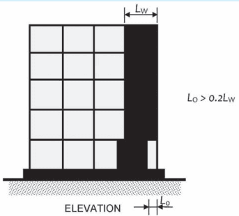
In-Plane Discontinuity in Vertical Elements Resisting Lateral ForceIn-plane discontinuity in vertical elements which are resisting lateral force shall be considered to exist, when in-plane offset of the lateral force resisting elements is greater than 20 percent of the plan length of those elements.In buildings with in-plane discontinuity and located in Seismic Zones II, the lateral drift of the building under the design lateral force shall be limited to 0.2 percent of the building height; in Seismic Zones III, IV and V, buildings with in-plane discontinuity shall not be permitted.
v)
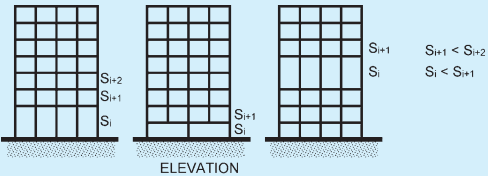
Strength Irregularity (Weak Storey)A weak storey is a storey whose lateral strength is less than that of the storey above.In such a case, buildings in Seismic Zones III, IV and V shall be designed such that safety of the building is not jeopardized; also, provisions of 5.4.10 shall be followed.
vi)
Floating or Stub ColumnsSuch columns are likely to cause concentrated damage in the structure.
PART 6 STRUCTURAL DESIGN — SECTION 1 LOADS, FORCES AND EFFECTS
OPENING LOCATED ANYWHERE IN THE SLAB
PLAN
OPENING LOCATED ALONG ANY EDGE OF THE SLAB
PLAN
13C FLOOR SLABS HAVING EXCESSIVE CUT-OUT AND OPENINGS
13D OUT-OF-PLANE OFFSETS IN VERTICAL ELEMENTS
13E NON-PARALLEL LATERAL FORCE SYSTEM:
(i) MOMENT FRAME BUILDING, and
(ii) MOMENT FRAME BUILDING WITH STRUCTURAL WALLS
FIG. 13 DEFINITIONS OF IRREGULAR BUILDINGS — PLAN IRREGULARITIES
14A STIFFNESS IRREGULARITY (SOFT STOREY)
ELEVATION
14B MASS IRREGULARITY
FIG. 14 — (Continued)
PART 6 STRUCTURAL DESIGN — SECTION 1 LOADS, FORCES AND EFFECTS
14D IN-PLANE DISCONTINUITY IN VERTICAL ELEMENTS RESISTING LATERAL FORCE
14E STRENGTH IRREGULARITY (WEAK STOREY)
FIG. 14 DEFINITIONS OF IRREGULAR BUILDINGS — VERTICAL IRREGULARITIES
5.4.2Lateral Force
5.4.2.1 Design lateral force
Buildings shall be designed for the design lateral force VB given by:
VB=AhW
where Ah shall be estimated as per 5.3.4.2, and W as per 5.4.4.
5.4.2.2 Minimum design lateral force
Buildings and portions there of shall be designed and constructed to resist at least the effects of design lateral force specified in 5.4.2.1. But, regardless of design earthquake forces arrived at as per 5.4.3.1, buildings shall have lateral load resisting systems capable of resisting a horizontal force not less than (VB)min as given in Table 46.
Table 46Minimum Design Earthquake Horizontal Lateral Force for Buildings (Clause 5.4.2.2)
SlNo.(1)
Seismic Zone(2)
ρpercent(3)
i)
II
0.7
ii)
III
1.1
iii)
IV
1.6
iv)
V
2.4
5.4.2.3 Importance factor (I)
In estimating design lateral force VB of buildings as per 5.4.2.1, the importance factor I of buildings shall be taken as per Table 47.
Table 47Importance Factor (I) (Clause 5.4.2.3)
Sl No.
Structure
I
(1)
(2)
(3)
i)
Important service and community buildings or structures (for example critical governance buildings, schools), signature buildings, monument buildings, lifeline and emergency buildings (for example hospital buildings, telephone exchange buildings, television station buildings, radio station buildings, bus station buildings, metro rail buildings and metro rail station buildings), railway stations, airports, food storage buildings (such as warehouses), fuel station buildings, electric power station buildings, and fire station buildings), and large community hall buildings (for example cinema halls, shopping malls, assembly halls and subway stations) and power station buildings
1.5
ii)
Residential or commercial buildings [other than those listed in Sl No. (i)] with occupancy more than 200 persons
1.2
iii)
All other buildings
1.0
NOTES
1 Owners and design engineers of buildings or structures may choose values of importance factor I more than those mentioned above.
2 Buildings or structures covered under Sl No. (iii) may be designed for higher value of importance factor I, depending on economy and strategy.
3 In Sl No. (ii), when a building is composed of more than one structurally independent unit, the occupancy size shall be for each of the structurally independent unit of the building.
4 In buildings with mixed occupancies, wherein different I factors applicable for the respective occupancies, larger of the importance factor I values shall be used for estimating the design earthquake force of the building.
5.4.2.4 Damping ratio
The value of damping shall be taken as 5 percent of critical damping for the purposes of estimating Ah in the design lateral force VB of a building as per 5.4.2.1, irrespective of the material of construction (namely steel, reinforced concrete, masonry, or a combination thereof of these three basic materials) of its lateral load resisting system, considering that buildings experience inelastic deformations under design level earthquake effects, resulting in much higher energy dissipation than that due to initial structural damping in buildings. This value of damping shall be used, irrespective of the method of the structural analysis employed, namely Equivalent Static Method (as per 5.4.6) or Dynamic Analysis Method (as per 5.4.7).
5.4.2.5 Design acceleration spectrum
Design acceleration coefficient Sa/g corresponding to 5 percent damping for different soil types, normalized to peak ground acceleration, corresponding to natural period T of structure considering soil-structure interaction,
irrespective of the material of construction of the structure. Sa/g shall be as given by expressions in 5.3.4.2.
5.4.2.6 Response reduction factor (R)
Response reduction factor, along with damping during extreme shaking and redundancy: (a) influences the nonlinear behaviour of buildings during strong earthquake shaking, and (b) accounts for inherent system ductility, redundancy and overstrength normally available in buildings, if designed and detailed as per this Section and the associated Indian Standards.
For the purpose of design as per this Section, response reduction factor R for different building systems shall be as given in Table 48. The values of R shall be used for design of buildings with lateral load resisting elements, and NOT for just the lateral load resisting elements, which are built in isolation.
5.4.2.7 Dual system
Buildings with dual system consist of moment resisting frames and structural walls (or of moment resisting frames and bracings) such that both of the following conditions are valid:
a) Two systems are designed to resist total design lateral force in proportion to their lateral stiffness, considering interaction of two systems at all floor levels; and
b) Moment resisting frames are designed to resist independently at least 25 percent of the design base shear.
5.4.3 Design Imposed Loads for Earthquake Force Calculation
5.4.3.1 For various loading classes specified in 3, design seismic force shall be estimated using full dead load plus percentage of imposed load as given in Table 49. The same shall be used in the three-dimensional dynamic analysis of buildings also.
5.4.3.2 For calculation of design seismic forces of buildings, imposed load on roof need not be considered. But, weights of equipment and other permanently fixed facilities should be considered; in such a case, the reductions of imposed loads mentioned in Table 49 are not applicable to that part of the load.
5.4.3.3 Imposed load values indicated in Table 49 for calculating design earthquake lateral forces are applicable to normal conditions. When loads during earthquakes are more accurately assessed, designers may alter imposed load values indicated or even replace the entire imposed load given in Table 49 with actual assessed load values, subject to the values given in Table 46 as the minimum values. Where imposed load is not assessed as per 5.4.3.1 and 5.4.3.2,
a) only that part of imposed load, which possesses mass, shall be considered; and
b) lateral earthquake design force shall not be calculated on contribution of impact effects from imposed loads.
PART 6 STRUCTURAL DESIGN — SECTION 1 LOADS, FORCES AND EFFECTS
Table 48Response Reduction Factor R for Building Systems (Clause 5.4.2.6)
Sl No.(1)
Lateral Load Resisting System(2)
R(3)
i)
Moment Frame Systems
a) RC buildings with ordinary moment resisting frame (OMRF) (see Note 1)
3.0
b) RC buildings with special moment resisting frame (SMRF)
5.0
c) Steel buildings with ordinary moment resisting frame (OMRF) (see Note 1)
3.0
d) Steel buildings with special moment resisting frame (SMRF)
5.0
ii)
Braced Frame Systems (see Note 2)
a) Buildings with ordinary braced frame (OBF) having concentric braces
4.0
b) Buildings with special braced frame (SBF) having concentric braces
4.5
c) Buildings with special braced frame (SBF) having eccentric braces
5.0
iii)
Structural Wall Systems (see Note 3)
a) Load bearing masonry buildings
1) Unreinforced masonry {designed as per good practice [6-1(19)]} without horizontal RC seismic bands (see Note 1)
1.5
2) Unreinforced masonry {designed as per good practice [6-1(19)]} with horizontal RC seismic bands
2.0
3) Unreinforced masonry {designed as per good practice [6-1(19)]} with horizontal RC seismic bands and vertical reinforcing bars at corners of rooms and jambs of openings {with reinforcement as per good practice [6-1(20)]}
2.5
4) Reinforced masonry [see Part 6 'Structural Design, Section 4 Masonry' of the Code]
3.0
5) Confined masonry
3.0
b) Buildings with ordinary RC structural walls (see Note 1)
3.0
c) Buildings with ductile RC structural walls
4.0
iv)
Dual Systems (see Note 3)
a) Buildings with ordinary RC structural walls and RC OMRFs (see Note 1)
3.0
b) Buildings with ordinary RC structural walls and RC SMRFs (see Note 1)
4.0
c) Buildings with ductile RC structural walls with RC OMRFs (see Note 1)
4.0
d) Buildings with ductile RC structural walls with RC SMRFs
5.0
v)
Flat Slab - Structural Wall Systems (see Note 4)
RC building with the three features given below:
3.0
a) Ductile RC structural walls (which are designed to resist 100 percent of the design lateral force),b) Perimeter RC SMRFs (which are designed to independently resist 25 percent of the design lateral force), and preferablyc) An outrigger and belt truss system connecting the core ductile RC structural walls and the perimeter RC SMRFs (see Note 1).
NOTES
1 RC and steel structures in Seismic Zones III, IV and V shall be designed to be ductile. Hence, this system is not allowed in these seismic zones.2 Eccentric braces shall be used only with SBFs.3 Buildings with structural walls also include buildings having structural walls and moment frames, but where,a) frames are not designed to carry design lateral loads, orb) frames are designed to carry design lateral loads, but do not fulfill the requirements of 'dual systems'.4 In these buildings, (a) punching shear failure shall be avoided, and (b) lateral drift at the roof under design lateral force shall not exceed 0.1 percent.
Table 49Percentage of Imposed Load to be Considered in Calculation of Seismic Weight (Clauses 5.4.3.1)
Sl No.
Imposed Uniformity Distributed Floor Loads kN/m2
Percentage of Imposed Load
(1)
(2)
(3)
i)
Up to and including 3.0
25
ii)
Above 3.0
50
5.4.3.4 Loads other than those given above (for example snow and permanent equipment) shall be considered appropriately.
5.4.3.5 In regions of severe snow loads and sand storms exceeding intensity of 1.5kN/m2 , 20 percent of uniform design snow load or sand load respectively, shall be included in the estimation of seismic weight. In case the minimum values of seismic weights corresponding to these load effects given in 2, 3, 4, 6 and 7 are higher, the higher values shall be used.
5.4.3.6 In buildings that have interior partitions, the weight of these partitions on floors shall be included in the estimation of seismic weight; this value shall not
be less than 0.5kN/m2 . In case the minimum values of seismic weights corresponding to partitions given in 2, 3, 4, 6 and 7 are higher, the higher values shall be used. It shall be ensured that the weights of these partitions shall be considered only in estimating inertial effects of the building.
5.4.4 Seismic Weight
5.4.4.1 Seismic weight of floors
Seismic weight of each floor is its full dead load plus appropriate amount of imposed load, as specified in 5.4.3. While computing the seismic weight of each floor, the weight of columns and walls in any storey shall be appropriately apportioned to the floors above and below the storey.
5.4.4.2 Any weight supported in between storeys shall be distributed to floors above and below in inverse proportion to its distance from the floors.