Distribution of Lateral Forces in the Piers of a Masonry Wall
G-1 Masonry walls are often seen to be perforated to make arrangement for windows and doors. The distribution of lateral force in a masonry wall is dependent on the position of the openings and the relative rigidity of the masonry piers created due to the presence of the openings in the masonry wall. The
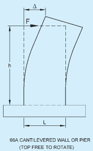
relative rigidity is dependent on the height by length ratio of the piers and the end conditions of those masonry piers as the deflection of the masonry piers due to horizontal loading changes due to the end condition of the piers (see Fig. 66). Here is a simple process is described which can be used to distribute
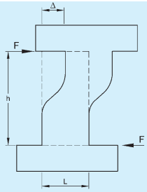
FIG. 66 DEFLECTION DUE TO END CONDITIONS OF PIERS
PART 6 STRUCTURAL DESIGN — SECTION 4 MASONRY
the lateral force in a wall which can be considered to be consist of some piers with some specific arrangements.
G-2 In any kind of placing of opening, the wall can be represented as a horizontal and vertical combination of piers with their respective end condition which will be used to find out their rigidities. Where large openings occur, it is difficult to obtain effective coupling of the wall segments or piers. If the wall is analysed as a horizontal combination of piers as shown in Fig. 67A and the combined rigidity
where are the rigidities of the piers 1, 2, 3, respectively.
If the segments are combined vertically, as shown in Fig. 67B, the combined rigidity can be calculated as:
Where are the rigidities of the piers 1, 2 and 3, respectively. Combination of these two types can be used to find the effective relative stiffness of a masonry wall.
The expression ignores the rotations that occur at the tops of segment 2 and 3 and therefore overestimates the rigidity of the wall. Along with this, it is valid only for the application of loads at the top level of the building.
As already said the rigidity R of the pier is dependent on its dimensions, modulus of elasticity E, modulus of rigidity G, and the support conditions. For a cantilever pier the displacement due to combined action of bending and shear is:
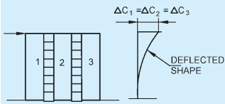
67A HORIZONTAL COMBINATION OF WALL SEGMENTS
where
horizontal force applied to the pier,
height of the pier,
moment of inertia of pier
length of the pier, and
thickness of pier.
So displacement of the cantilever pier is:
The rigidity of a wall is proportional to the inverse of the deflection. For cantilever walls the rigidity will be:
For a pier with both ends fixed against rotation the deflection due to combined action of bending and shear will be:
Values of for different ratio can be taken from the chart in the Fig. 68.
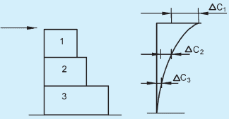
67B VERTICAL COMBINATION OF WALL SEGMENTS
FIG. 67 WALL COMBINBATIONS FOR CALCULATING RIGIDITIES OF WALLS WITH OPENINGS
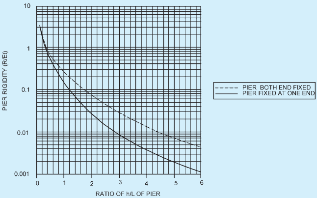
FIG. 68 CHARTS FOR CALCULATING WALL RIGIDITIES
From the relations given in equations above it is found that the relative contributions of the bending and shear deformation depend on the wall aspect ratio and therefore, the rigidity varies over the height of the building. For high h/L ratios, the effect of shear deformation is very small and calculation of pier rigidities based on flexural stiffness is relatively accurate. For very squat walls (with h/L < 0.25), rigidities based on shear deformation are reasonably accurate, but for intermediate walls with h/L from 0.25 to 4, both components of relative rigidity should be considered.
G-3 The method is explained further explained by one illustration. For the wall as shown in Fig. 69,
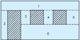
FIG. 69 WALL WITH OPENINGS (CALCULATION OF RIGIDITY AND LOAD DISTRIBUTION)
(Vertical combination)
where
(Vertical combination)
PART 6 STRUCTURAL DESIGN — SECTION 4 MASONRY