8.1 The design of joints shall be made in the light of their assessment with respect to the following considerations:
a) Feasibility — The feasibility of a joint shall be determined by its load carrying capacity in the particular situation in which the joint is to function.
b) Practicability — Practicability of joint shall be determined by the amount and type of material required in construction; cost of material, fabrication and erection and the time for fabrication and erection.
c) Serviceability — Serviceability shall be determined by the joints/expected behaviour to repeated or possible overloading and exposure to climatic or chemical conditions.
d) Fire rating — The fire rating for joints of precast components shall be higher or at least equal to connecting members.
NOTE — Fire resistance testing under sustained loading may also be carried out on a prototype, as mutually agreed to between the parties concerned.
e) Appearance — The appearance of precast components' joints shall merge with architectural aesthetic appearance and shall not be physically prominent compared to other parts of structural components.
f) Water tightness of joints — In buildings, the external joints between precast elements should be water tight to ensure the durability requirements. If the joints are not water tight, it may lead to corrosion of reinforcing steel due to exposure to moisture thereby impacting the structural integrity. Also, water can enter inside the building and impact the functionality in service life of the building. In case of precast reinforced concrete wall buildings, joints of external walls, in addition to their structural efficiency, shall be watertight. For non-load bearing/façade walls the connections shall allow free movement of
the walls due to temperature changes. This can be achieved by suitably shaping the joint or by sealing compounds. In load bearing external walls, the horizontal and vertical joints shall be filled with non-shrink non-metallic high strength cementitious grout followed by backer rod (bond breaker such as polyethylene film also can be used in place of backer rod) with sealant at the external side. The sealing compound shall be approved by the Engineer-in-Charge and shall have a long life to avoid frequent repair of the joints. It should be noted that the sealant is provided as an additional line of defense against water entry. In cases of moderate water exposure, the joints could be detailed with cement grout only with appropriate additional water proofing treatment instead of sealant (see 9.4).
8.2 The following are the requirements of a structural joint:
a) It shall be capable of being designed to transfer the imposed load and moments with a known margin of safety;
b) It shall occur at logical locations in the structure and at points which may be most readily analyzed and easily reinforced;
c) It shall accept the loads without marked displacement or rotation and avoid high local stresses;
d) It shall accommodate tolerances in elements;
e) It shall require little temporary support, permit adjustment and demand only a few distinct operation to make;
f) It shall permit effective inspection and rectification;
g) It shall be reliable in service with other parts of the building; and
h) It shall enable the structure to absorb sufficient energy during earthquakes so as to avoid sudden failure of the structure (see Note). The joint should be ductile.
NOTE — If required, tests may be carried out on prototypes to assess against the above requirement.
8.2.1 Precast structures may have continuous or hinged connections subject to providing sufficient rigidity to withstand horizontal loading. When only compressive forces are to be taken, hinged joints may be adopted. In case of prefabricated concrete elements, load is transmitted via the concrete. When both compressive force and bending moment are to be taken, rigid or welded joints may be adopted; the shearing force is usually small in the column and can be taken up by the friction resistance of the joint. Here load transmission is accomplished by steel inserted parts together with concrete. In precast structures, it is critical to minimize
relative movements of precast components under loads. Hence, connection details that rely solely on the frictional resistance under gravity loads are not permitted. The connections shall be designed using either the pure shear capacity of the connection element or based on the shear friction theory that takes the advantage of the frictional resistance of concrete components under gravity loads.
8.2.2 When considering thermal shrinkage and heat effects, provision of freedom of movement or introduction of restraint may be considered.
8.3 Following connections and jointing techniques/materials may be employed:
a) Welding of cleats or projecting steel,
b) Overlapping reinforcement, loops and linking steel grouted by concrete,
c) Reinforced concrete ties all round a slab,
d) Prestressing,
e) Epoxy grouting,
f) Cement/lime grout with non-shrink additive,
g) Polymer slurry grouting at dowel cast bolts and nuts connection,
h) Rebar fastener, chemical fastener and expansion fastener,
j) Reinforcement coupler,
k) Combination of the above, and
m) Any other method proven by test.
8.4 Precast Joint details
Some of the typical precast joint details have been illustrated in Fig. 7 to Fig. 24.
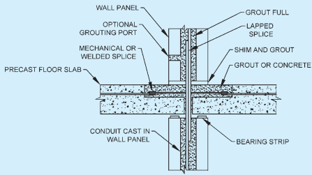
SECTION AT JOINT
NOTE — Overlapping bars in grout-filled conduit are extended full-height through the structural element.
FIG. 7 LAPPED SPLICES IN LARGE CONDUIT
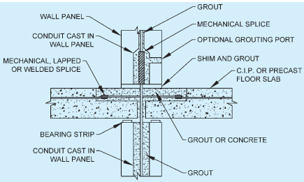
NOTE — Vertical bars in conduit are spliced and the system is grouted.
FIG. 8 MECHANICAL CONNECTION IN CONDUIT
PART 6 STRUCTURAL DESIGN — SECTION 7 PREFABRICATION, SYSTEMS BUILDING AND MIXED/COMPOSITE CONSTRUCTION: 7A PREFABRICATED CONCRETE

FIG. 9 DIFFERENT TYPES OF MECHANICAL SPLICES FOR CONNECTION OF VARIOUS CONFIGURATIONS OF PRECAST WALLS AND FLOORS
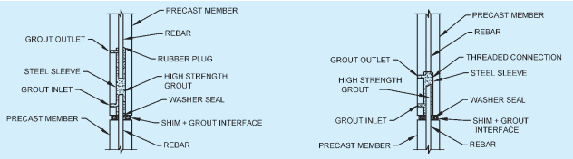
FIG. 10 SOME MECHANICAL SPLICES USING HIGH-STRENGTH NON-SHRINK GROUT

FIG. 11 VARIATIONS OF SPLICES AND CAST-IN-PLACE CLOSURE PLACEMENTS TO CREATE VERTICAL JOINTS BETWEEN PRECAST CONCRETE ELEMENTS