Masonry structures gain stability from the support offered by cross walls, floors, roof and other elements such as piers and buttresses. Load bearing walls are structurally more efficient when the load is uniformly distributed and the structure is so planned that eccentricity of loading on the members is as small as possible. Avoidance of eccentric loading by providing adequate bearing of floor/roof on the walls providing adequate stiffness in slabs and avoiding fixity at the supports, etc, is especially important in load bearing walls in multistorey structures. These matters should receive careful consideration during the planning stage of masonry structures.
4.2Lateral Supports and Stability
4.2.1 Lateral Supports
Lateral supports for a masonry element such as load bearing wall or column are intended,
a) to limit slenderness of a masonry element so as to prevent or reduce possibility of buckling of the member due to vertical loads; and
b) to resist horizontal components of forces so as to ensure stability of a structure against overturning.
4.2.1.1 Lateral support may be in the vertical or horizontal direction, the former consisting of floor/roof bearing on the wall or properly anchored to the same and latter consisting of cross walls, piers or buttresses.
4.2.1.2 Requirements of 4.2.1(a) from consideration of slenderness may be deemed to have been met with, if
a) in case of a wall, where slenderness ratio is based on effective height, any of the following
constructions are provided:
RCC floor/roof slab (or beams and slab) irrespective of the direction of span, bears on the supported wall as well as cross walls, to the extent of at least 90 mm;
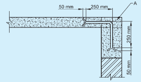
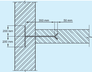
RCC floor/roof slab not bearing on the supported wall or cross wall is anchored to it with non-corrodible metal ties of 600 mm length and of section not less than 6 mm × 30 mm, and at intervals not exceeding 2 m, as shown in Fig. 5; and
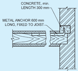
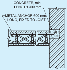
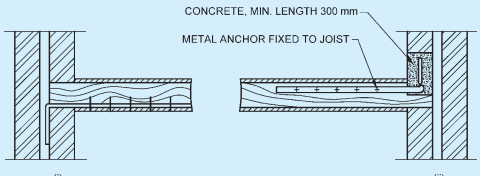
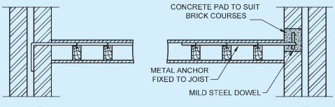
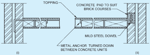
Timber floor/roof, anchored by non-corrodible metal ties of length 600 mm and of minimum section 6 mm × 30 mm, securely fastened to joists and built into walls as shown in Fig. 6 and Fig. 7. The anchors shall be provided in the direction of span of timber joists as well as in its perpendicular direction, at intervals of not more than 2 m in buildings up to two storeys and 1.25 m for buildings more than two storeys in height.
1 In case precast RCC units are used for floors and roofs, it is necessary to interconnect them and suitably anchor them to the cross walls so that they can transfer lateral forces to the cross walls.
2 In case of small houses of conventional designs, not exceeding two storeys in height, stiffening effect of partitions and cross walls is such that metal anchors are normally not necessary in case of timber floor/roof and precast RCC floor/roof units.
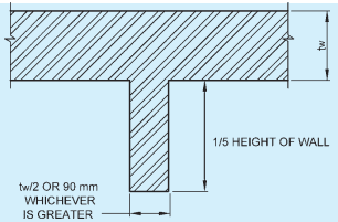
b) in case of a wall, when slenderness ratio is based on its effective length; a cross wall/pier/buttress of thickness equal to or more than half the thickness of the supported wall or 90 mm, whichever is more, and length equal to or more than one fifth of the height of wall, is built at right angle to the wall (see Fig. 8) and bonded to it according to provision of 4.2.2.2 (d);
c) in case of a column, an RCC or timber beam/RS joist/roof truss, is supported on the column.
A = Cement concrete only at places where anchors are provided (200 mm in width in the direction perpendicular to the plane of paper)
FIG. 5 ANCHORING OF RCC SLAB WITH MASONRY WALL (WHEN SLAB DOES NOT BEAR ON WALL)
PART 6 STRUCTURAL DESIGN — SECTION 4 MASONRY
6A JOISTS AT RIGHT ANGLE TO WALL
6B JOISTS PARALLEL TO WALL
FIG. 6 TYPICAL DETAILS FOR ANCHORAGE OF SOLID WALLS
7A TIMBER JOISTS AT RIGHT ANGLES TO WALL
7B TIMBER JOISTS PARALLEL TO WALL
7C PRECAST CONCRETE FLOOR UNITS PARALLEL TO WALL
FIG. 7 TYPICAL DETAILS FOR ANCHORAGE OF CAVITY WALLS
In this case, the column will not be deemed to be laterally supported in the direction at right angle to it; and
d) in case of a column, an RCC beam forming a part of beam and slab construction is supported on the column, and slab adequately bears on stiffening walls. This construction will provide lateral support to the column, in the direction of both horizontal axes.
FIG. 8 MINIMUM DIMENSION FOR MASONRY WALL OR BUTTRESS EFFECTIVE LATERAL SUPPORT
4.2.2 Stability
A wall or column subjected to vertical and lateral loads may be considered to be provided with adequate lateral support from consideration of stability, if the construction providing the support is capable of resisting some of the following forces:
a) Simple static reactions at the point of lateral support to all the lateral loads; plus
b) 2.5 percent of the total vertical load that the wall or column is designed to carry at the point of lateral support.
4.2.2.1 For the purpose specified in 4.2.2, if the lateral supports are in the vertical direction, these should meet the requirements given in 4.2.1.2 (a) and should also be capable of acting as horizontal girders duly anchored to the cross wall so as to transmit the lateral loads to the foundations without exceeding the permissible stresses in the cross walls.
4.2.2.2 In case of load bearing buildings up to four storeys, stability requirements of 4.2.2 may be deemed to have been met with, if
a) height to width ratio of building does not exceed 2;
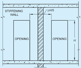
b) cross walls acting as stiffening walls continuous from outer wall to outer wall or outer wall to a load bearing inner wall, and of thickness and spacings as given in Table 3 are provided. If stiffening wall or walls that are in a line, are interrupted by openings, length of solid wall
PART 6 STRUCTURAL DESIGN — SECTION 4 MASONRY
or walls in the zone of the wall that is to be stiffened shall be at least one-fifth of height of the opening as shown in Fig. 9;
c) floors and roof either bear on cross walls or are anchored to those walls as in 4.2.1.2 such that all lateral loads are safely transmitted to those walls and through them to the foundation; and
d) cross walls are built jointly with the bearing walls and are jointly mortared, or the two interconnected by toothing. Alternatively, cross walls may be anchored to walls to be supported by ties of non-corrodible metal of minimum section 6 mm×35 mm and length 600 mm with ends bend at least 50 mm; maximum vertical spacing of ties being 1.2 m (see Fig. 10).
4.2.2.3 In case of halls exceeding 8.0 m in length, safety and adequacy of lateral supports shall always be checked by structural analysis.
Table 3Thickness and Spacing of Stiffening Walls [Clause 4.2.2.2(b)]
Sl No.
Thickness of Load Bearing Wall to be Stiffened mm
Height1) of Storey Not to Exceed m
Stiffening Wall 1)
Thickness not Less than
Maximum Spacing m
1 to 3 Storeys mm (4)
4 Storeys mm (5)
(1)
(2)
(3)
(6)
i)
100
3.2
100
—
4.5
ii)
200
3.2
100
200
6.0
iii)
300
3.4
100
200
8.0
iv)
Above 300
5.0
100
200
8.0
1) Storey height and maximum spacings as given are centre-to-centre dimensions.
FIG. 9 OPENING IN STIFFENING WALL
FIG. 10 ANCHORING OF STIFFENING WALL WITH SUPPORT WALL
4.2.2.4 A trussed roofing may not provide lateral support unless special measures are adopted to brace and anchor the roofing. However, in case of residential and similar buildings of conventional design with trussed roofing having cross walls, it may be assumed that stability
requirements are met with by the cross walls and structural analysis for stability may be dispensed with.
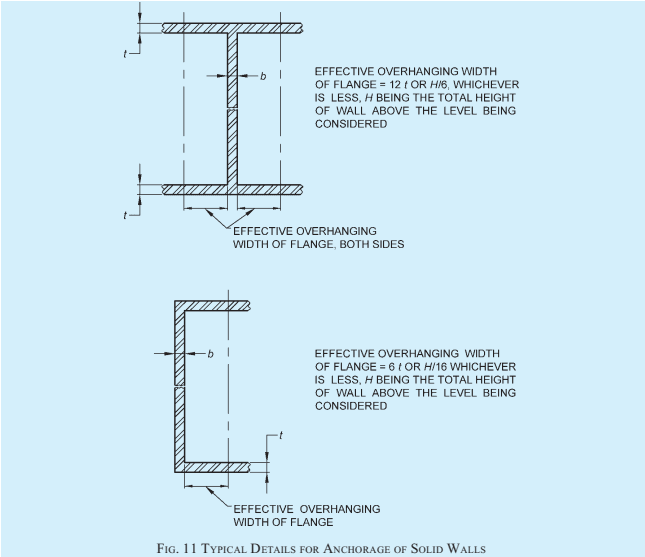
4.2.2.5 Capacity of a cross wall, also called shear wall, sometimes to take horizontal loads and consequently bending moments increases, when parts of bearing walls act as flanges to the cross wall. Maximum overhanging length of bearing wall which could effectively function as a flange should be taken as 12 t or H/6, whichever is less in case of T/I shaped walls, and 6 t or H/16, whichever is less in case of L/U shaped walls, where t is the thickness of bearing wall and H is the total height of wall above the level being considered, as shown in Fig. 11.
4.2.2.6 External walls of basement and plinth
In case of external walls of basement and plinth, stability requirements of 4.2.2 may be deemed to have been met with, if
a) bricks used in basement and plinth have a minimum crushing strength of 5N/mm2 and mortar used in masonry is of Grade M1 or better;
b) clear height of ceiling in basement does not exceed 2.6 m;
c) walls are stiffened according to provisions of 4.2.2.1;
d) in the zone of action of soil pressure on basement walls, traffic load excluding any surcharge due to adjoining buildings does not exceed 5kN/m2 and terrain does not rise; and
e) minimum thickness of basement walls is in accordance with Table 4. However, if percentage opening in the basement wall for purposes like ventilation are more than 25 percent, then stability analysis/check need to be performed particularly for resistance to seismic loads.
NOTE — In case there is surcharge on basement walls from adjoining buildings, thickness of basement walls shall be based on structural analysis.
Table 4Minimum Thickness of Basement Walls [Clause 4.2.2.6(e)]
Sl No.
Height of the Ground Above Basement Floor Level
Minimum Nominal Thickness of Basement Wall
Wall Loading (Permanent Load) Less than 50 kN/m
Wall Loading (Permanent Load) More than 50 kN/m
(1)
(2)
(3)
mm(4)
i)
Up to 1.4 m
Up to 1.75 m
300
ii)
Up to 2 m
Up to 2.5 m
400
4.2.2.7 Walls mainly subjected to lateral loads
a) Free standing wall — A free standing wall such as compound wall or parapet wall is acted upon by wind force which tends to overturn it. This tendency to over-turning is resisted by gravity force due to self-weight of wall, and also by flexural moment of resistance on account of tensile strength of masonry. Free standing walls shall thus be designed as in 5.5.2.1. If mortar used for masonry cannot be relied upon for taking flexural tension (see 5.4.2), stability of free standing wall shall be ensured such that stability moment of wall due to self-weight equals or exceeds 1.5 times the overturning moment.
b) Retaining wall — Stability for retaining walls shall normally be achieved through gravity action but flexural moment of resistance could also be taken advantage of under special circumstances at the discretion of the designer (see 5.4.2).
4.3Effective Height
4.3.1 Wall
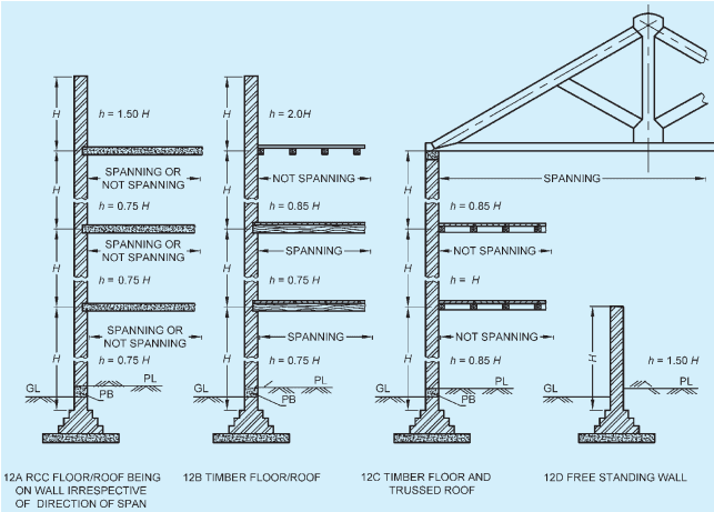
Effective height of a wall shall be taken as shown in Table 5 (see Fig. 12).
NOTE — A roof truss or beam supported on a column meeting the requirements of 4.2.2.1 is deemed to provide lateral support to the column only in the direction of the beam/truss.
Table 5Effective Height of Walls (Clause 4.3.1)
Sl No.(1)
Condition of Support(2)
Effective Height(3)
i) Lateral as well as rotational restraint (that is, full restraint) at top and bottom. For example, when the floor/roof spans on the walls so that reaction to load of floor/roof is provided by the walls, or when an RCC floor/roof has bearing on the wall (minimum 90 mm), irrespective of the direction of the span foundation footings of a wall give lateral as well as rotational restraint 0.75 H
ii) Lateral as well as rotational restraint (that is, full restraint) at one end and only lateral restraint (that is, partial restraint) at the other. For example, RCC floor/roof at one end spanning or adequately bearing on the wall and timber floor/roof not spanning on wall, but adequately anchored to it, on the other end 0.85 H
iii) Lateral restraint, without rotational restraint (that is, partial restraint) on both ends. For example, timber floor/roof, not spanning on the wall but adequately anchored to it on both ends of the wall, that is, top and bottom 1.00 H
iv) Lateral restraint as well as rotational restraint (that is, full restraint) at bottom but have no restraint at the top. For example, parapet walls with RCC roof having adequate bearing on the lower wall, or a compound wall with proper foundation on the soil. 1.50 H
1 H is the height of wall between centres of support in case of RCC slabs and timber floors. In case of footings or foundation block, height (H) is measured from top of footing or foundation block. In case of roof truss, height (H) is measured up to bottom of the tie beam. In case of beam and slab construction, height should be measured from centre of bottom slab to centre of top beam. All these cases are illustrated by means of examples shown in Fig. 12.
2 For working out effective height, it is assumed that concrete DPC, when properly bonded with masonry, does not cause discontinuity in the wall.
3 Where membrane type damp-proof course or termite shield causes a discontinuity in bond, the effective height of wall may be taken to be greater of the two values calculated as follows :
a) Consider H from top of footing ignoring DPC and take effective height as 0.75H.
b) Consider H from top of DPC and take effective height as 0.85 H.
4 When assessing effective height of walls, floors not adequately anchored to walls shall not be considered as providing lateral support to such walls.
5 When thickness of a wall bonded to a pier is at least two-thirds of the thickness of the pier measured in the same direction, the wall and pier may be deemed to act as one structural element.
PART 6 STRUCTURAL DESIGN — SECTION 4 MASONRY
NOTE — If plinth band (PB) is equal to or more than 150 mm, height can be taken from above the plinth band.
FIG. 12 EFFECTIVE HEIGHT OF WALL
4.3.2 Column
In case of a column, effective height shall be taken as actual height for the direction it is laterally supported and as twice the actual height for the direction it is not laterally supported (see Fig. 13).
1 A roof truss or beam supported on a column meeting the requirements of 4.2.2.1 is deemed to provide lateral support to the column only in the direction of the beam/truss.
2 When floor or roof consisting of RCC beams and slabs is supported on columns, the columns would be deemed to be laterally supported in both directions.
4.3.3 Openings in Walls
When openings occur in a wall such that masonry between the openings is by definition a column, effective height of masonry between the openings shall be reckoned as follows:
a) When wall has full restraint at the top:
Effective height for the direction
perpendicular to plane of wall equals 0.75H plus 0.25H1, where H is the distance between supports and H1 is the height of the taller opening; and
Effective height for the direction parallel to the wall equals H, that is, the distance between the supports.
b) When wall has partial restraint at the top and bottom:
Effective height for the direction perpendicular to plane of wall equals H when height of neither opening exceeds 0.5H and it is equal to 2H when height of any opening exceeds 0.5H; and
Effective height for the direction parallel to the plane of the wall equals 2H.
4.5Effective Thickness
Effective thickness to be used for calculating slenderness ratio of a wall or column shall be obtained as in 4.5.1 to 4.5.5.
4.5.1 For solid walls, faced walls or columns, effective thickness shall be the actual thickness.
4.5.2 For solid walls adequately bonded into piers, buttresses, effective thickness for determining slenderness ratio based on effective height shall be the actual thickness of wall multiplied by stiffening coefficient as given in Table 7. No modification in effective thickness, however, shall be made when slenderness ratio is to be based on effective length of walls.
4.5.3 For solid walls or faced walls stiffened by cross
walls, appropriate stiffening coefficient may be determined from Table 7 on the assumption that the cross walls are equivalent to piers of width equal to the thickness of the cross wall and of thickness equal to three times the thickness of stiffened wall.
Sl No.
Ratio wpSp
Stiffening Coefficient
twtp=1
twtp=2
twtp=3 or more
(1)
(2)
(3)
(4)
(5)
i)
6
1.0
1.4
2.0
ii)
8
1.0
1.3
1.7
iii)
10
1.0
1.2
1.4
iv)
15
1.0
1.1
1.2
v)
20 or more
1.0
1.0
1.0
where Sp = centre-to-centre spacing of the pier or cross wall, tp = thickness of pier as defined in 2.1.3 (b) (see Fig. 1), tw = actual thickness of the wall proper (see Fig. 1), and wp = width of the pier in the direction of the wall or the actual thickness of the cross wall.NOTE — Linear interpolation between the values given in this table is permissible but not extrapolation outside the limits given.
4.5.4 For cavity walls with both leaves of uniform thickness throughout, effective thickness shall be taken as two-thirds of the sum of the actual thickness of the two leaves.
4.5.5 For cavity walls with one or both leaves adequately bonded into piers, buttresses or cross walls at intervals, the effective thickness of the cavity wall shall be two-thirds of the sum of the effective thickness of each of the two leaves; the effective thickness of each leaf being calculated using 4.5.1 or 4.5.2 as appropriate.
4.6Slenderness Ratio
4.6.1 Walls
For a wall, slenderness ratio shall be effective height divided by effective thickness or, effective length divided by the effective thickness, whichever is less. In case of a load bearing wall, slenderness ratio shall not exceed that given in Table 8. To reduce the slenderness ratio one and a half brick thick wall shall be up to ground level.
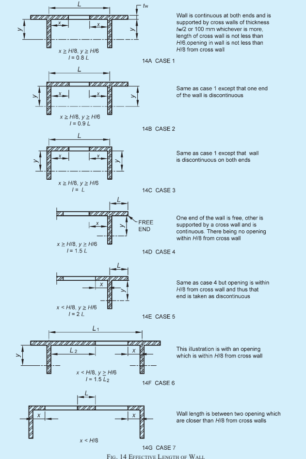
FIG. 14 EFFECTIVE LENGTH OF WALL
PART 6 STRUCTURAL DESIGN — SECTION 4 MASONRY
Sl No.
Number of Storeys
Maximum Slenderness Ratio
Using Portland Cement or Portland Pozzolana Cement in Mortar
Using Lime Mortar
(1)
(2)
(3)
(4)
i)
Not exceeding 2
27
20
ii)
Exceeding 2
27
13
4.6.2 Columns
For a column, slenderness ratio shall be taken to be the greater of the ratios of effective heights to the respective effective thickness, in the two principal directions. Slenderness ratio for a load bearing column shall not exceed 12.
4.7 Eccentricity
Eccentricity of vertical loading at a particular junction in a masonry wall shall depend on factors, such as extent of bearing, magnitude of loads, stiffness of slab or beam, fixity at the support and constructional details at junctions. No exact calculations are possible to make accurate assessment of eccentricity. Extent of eccentricity under any particular circumstances has, therefore, to be decided according to the best judgment of the designer. Some guidelines for assessment of eccentricity are given in Annex A.