22.0 Effective Depth
Effective depth of a beam is the distance between the centroid of the area of tension reinforcement and the maximum compression fibre, excluding the thickness of finishing material not placed monolithically with the member and the thickness of any concrete provided to allow for wear. This will not apply to deep beams.
22.1 T-Beams and L-Beams
22.1.1 General
A slab which is assumed to act as a compression flange of a T-beam or L-beam shall satisfy the following:
a) The slab shall be cast integrally with the web, or the web and the slab shall be effectively bonded together in any other manner; and
b) If the main reinforcement of the slab is parallel to the beam, transverse reinforcement shall be provided as in Fig. 3; such reinforcement shall not be less than 60 percent of the main reinforcement at mid span of the slab.
22.1.2 Effective Width of Flange
In the absence of more accurate determination, the effective width of flange may be taken as the following but in no case greater than the breadth of the web plus half the sum of the clear distances to the adjacent beams on either side:
a) For T-beams,
b) For L-beams,
c) For isolated beams, the effective flange width shall be obtained as below but in no case
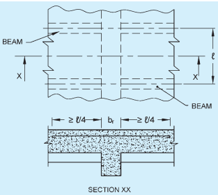
FIG. 3 TRANSVERSE REINFORCEMENT IN FLANGE OF T-BEAM WHEN MAIN REINFORCEMENT OF SLAB IS PARALLEL TO THE BEAM
greater than the actual width:
T-beams,
L-beams,
where
effective width of flange,
= distance between points of zero moments in the beam,
breadth of the web,
thickness of flange, and
b = actual width of the flange.
NOTE — For continuous beams and frames, may be assumed as 0.7 times the effective span.
PART 6 STRUCTURAL DESIGN — SECTION 5 CONCRETE: 5A PLAIN AND REINFORCED CONCRETE
22.2 Control of Deflection
The deflection of a structure or part thereof shall not adversely affect the appearance or efficiency of the structure or finishes or partitions. The deflection shall generally be limited to the following:
a) The final deflection due to all loads including the effects of temperature, creep and shrinkage and measured from the as-cast level of the supports of floors, roofs and all other horizontal members, should not normally exceed span/250.
b) The deflection including the effects of temperature, creep and shrinkage occurring after erection of partitions and the application of finishes should not normally exceed span/350 or 20 mm, whichever is less.
22.2.1 The vertical deflection limits may generally be assumed to be satisfied provided that the span to depth ratios are not greater than the values obtained as below:
a) Basic values of span to effective depth ratios for spans up to 10 m: Cantilever : 7 Simply supported : 20 Continuous : 26
b) For spans above 10 m, the values in (a) may be multiplied by 10/span in metres, except for cantilever in which case deflection calculations should be made.
c) Depending on the area and the stress of steel for tension reinforcement, the values in (a) or (b) shall be modified by multiplying with the modification factor obtained as per Fig. 4.
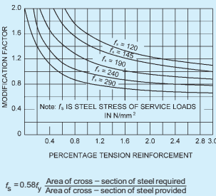
FIG. 4 MODIFICATION FACTOR FOR TENSION REINFORCEMENT
d) Depending on the area of compression reinforcement, the value of span to depth ratio be further modified by multiplying with the modification factor obtained as per Fig. 5.
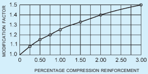
FIG. 5 MODIFICATION FACTOR FOR COMPRESSION REINFORCEMENT
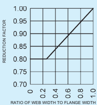
e) For flanged beams, the values of (a) or (b) be modified as per Fig. 6 and the reinforcement percentage for use in Fig. 4 and Fig. 5 should be based on area of section equal to . NOTE — When deflections are required to be calculated, the method given in Annex C may be used.
22.3 Slenderness Limits for Beams to Ensure Lateral Stability
A simply supported or continuous beam shall be so proportioned that the clear distance between the lateral restraints does not exceed or , whichever is less, where is the effective depth of the beam and the breadth of the compression face midway between the lateral restraints.