10.1 In large span structures, the members have to transmit very heavy stresses requiring stronger jointing techniques with metallic rings or wooden disc-dowels. Improvised metallic ring connector is a split circular band of steel made from mild steel pipes. This is placed in the grooves cut into the contact faces of the timber members to be joined, the assembly being held together by means of a connecting bolt (see Fig. 10).
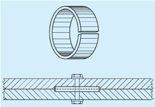
FIG. 10 SPLIT RING CONNECTOR
10.1.1 Dimensions of Members
Variation of thickness of central (main) and side members affect the load carrying capacity of the joint. The thickness of main member shall be at least 57 mm and that of side member 38 mm with length and width of members governed by placement of connector at joint.
The metallic connector shall be so placed that the loaded edge distance is not less than the diameter of the connector and the end distance not less than 1.75 times the diameter on the loaded side.
10.1.2 Design Considerations
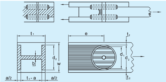
The primary stresses in a split ring connector joint under
tension are illustrated in Fig. 11. The shaded areas represent the part of wood in shear, compression and tension. Related formulae for the same are given in 10.1.2.1.
For fabrication of structural members, a hole of the required size of the bolt is drilled into the member and a groove is made on the contact faces of the joint.
Theoretical safe loads in design shall be corroborated with sample tests done in accordance with accepted standard [6-3A(10)].
NOTE — A pilot study on determination of strength of improvised split ring connector joint in a compression test for a specific design problem conducted using Mesua ferrea (Mesua), yielded the data which is given below, for guidance:
10.1.2.1 Strength of joint is controlled by one or another or combination of three properties:
a) Tension area (see Fig. 11A):
10.2 Wooden Disc-Dowel
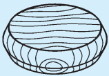
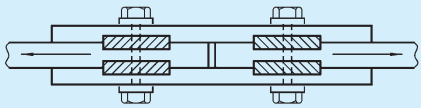
10.2.1 It is a circular hardwood disc generally tapered each way from the middle so as to form a double conical frustum. Such a disc is made to fit into preformed holes (recesses), half in one member and the other half in another, the assembly being held by one mild steel bolt through the centre of the disc to act as a coupling for keeping the jointed wooden members from spreading apart.
As timber always fails by shearing or crushing in front of bolts, the function of disc-dowel incorporated in the joint is to distribute the shearing stresses on a larger area of wood so as to transmit the full amount of stresses.
10.2.2 Dimensions of Members
The thickness of dowel may vary from 25 mm to 35 mm and diameter from 50 mm to 150 mm. The diameter of dowel shall be 3.25 to 3.50 times the thickness.
The edge clearance shall range from to as per the size of the dowel. The end clearance shall be at least equal to the diameter of dowel for joints subjected to tension and three-fourth the diameter for
compression joints. Disc dowel shall be turned from radial (quarter sawn) planks of seasoned material.
10.2.3 Choice of Species
Wood used for making dowels shall be fairly straight grained, free from excessive liability to shrink and warp, and retain shape well after seasoning and having high shear strength. Species recommended include,
a) Babul,
b) Dhaman,
c) Irul,
d) Sissoo,
e) Rose Wood,
f) Sandal,
g) Axle-Wood,
h) Padauk, and
j) Yon.
NOTE — Data on the above species are as per Table 1.
10.2.4 Design Considerations
The forces on dowel in a lap joint and butt joint are illustrated in Fig. 12. Dowel is subjected to shearing at the mid-section, and compression along the grain at the bearing surfaces. For equal strength in both the forces, formula equations are given in the Fig. 12 to determine the size of dowel.