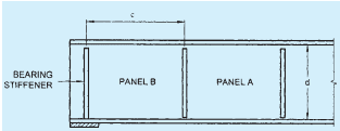
14.7.1.1 When the web of a member acting alone (that is, without stiffeners) proves inadequate, stiffeners for meeting the following requirements should be provided:
a) Intermediate transverse web stiffener — To improve the buckling strength of a slender web due to shear (see 14.7.2).
b) Load carrying stiffener — To prevent local buckling of the web due to concentrated loading (see 14.7.3 and 14.7.5).
c) Bearing stiffener — To prevent local crushing of the web due to concentrated loading (see 14.7.4 and 14.7.6).
d) Torsion stiffener — To provide torsional restraint to beams and girders at supports (see 14.7.9).
e) Diagonal stiffener — To provide local reinforcement to a web under shear and bearing (see 14.7.7).
f) Tension stiffener — To transmit tensile forces applied to a web through a flange (see 14.7.8).
The same stiffeners may perform more than one function and their design should comply with the requirements of all the functions for which designed.
14.7.1.2 Outstand of web stiffeners
Unless the outer edge is continuously stiffened, the outstand from the face of the web should not exceed 20tqε .
When the outstand of web stiffener is between 14tqε and 20tqε , then the stiffener design should be on the basis of a core section with an outstand of only 14tqε , where tq is the thickness of the stiffener.
14.7.1.3 Stiff bearing length
The stiff bearing length of any element, b1 , is that length which cannot deform appreciably in bending. To determine b1 , the dispersion of load through a steel bearing element should be taken as 45∘ through solid material, such as bearing plates, flange plates, etc (see Fig.15).
14.7.1.4 Eccentricity
Where a load or reaction is applied eccentric to the centerline of the web or where the centroid of the stiffener does not lie on the centerline of the web, the resulting eccentricity of loading should be accounted for in the design of the stiffener.
14.7.1.5 Buckling resistance of stiffeners
The buckling resistance Fqd should be based on the design compressive stress fcd (see 13.1.2.1) of a strut (curve c), the radius of gyration being taken about the axis parallel to the web. The effective section is the full area or core area of the stiffener (see 14.7.1.2) together with an effective length of web on each side of the centerline of the stiffeners, limited to 20 times the web thickness. The design strength used should be the minimum value obtained for buckling about the web or the stiffener.
The effective length for intermediate transverse stiffeners used in calculating the buckling resistance,
Fqd, should be taken as 0.7 times the length, L of the stiffener.
The effective length for load carrying web stiffeners used in calculating the buckling resistance, Fxd , assumes that the flange through which the load or reaction is applied is effectively restrained against lateral movement relative to the other flange, the effective length should be taken as:
a) KL=0.7L, when flange is restrained against rotation in the plane of the stiffener (by other structural elements), and
b) KL=L, when flange is not so restrained
where
L= length of the stiffener.
If the load or reaction is applied to the flange by a compression member, then unless effective lateral restraint is provided at that point, the stiffener should be designed as part of the compression member applying the load, and the connection between the column and beam flange shall be checked for the effects of the strut action.
14.7.2 Design of Intermediate Transverse Web Stiffeners
14.7.2.1 General
Intermediate transverse stiffeners may be provided on one or both sides of the web.
14.7.2.2 Spacing
Spacing of intermediate stiffeners, where provided, shall comply with 14.6.1 depending on the thickness of the web.
14.7.2.3 Outstand of stiffeners
The outstand of the stiffeners should comply with 14.7.1.2.
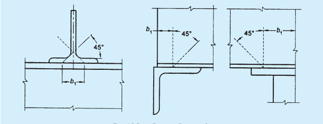
FIG. 15 STIFF BEARING LENGTH, b1
PART 6 STRUCTURAL DESIGN — SECTION 6 STEEL
14.7.2.4 Minimum stiffeners
Transverse web stiffeners not subject to external loads or moments should have a second moment of area, Is about the centreline of the web, if stiffeners are on both sides of the web and about the face of the web, if single stiffener on only one side of the web is used such that:
where
d= depth of the web;
tw = minimum required web thickness for spacing using tension field action, as given in 14.4.2.1; and
c= actual stiffener spacing.
Stiffeners not subjected to external loads or moments should be checked for a stiffener force:
where
Fqd=design resistance of the intermediate stiffeners;
V= factored shear force adjacent to the stiffener; and
Vcr = shear buckling resistance of the web panel designed without using tension field action as given in 14.4.2.2 a).
Stiffeners subject to external loads and moments should meet the conditions for load carrying web stiffeners in 14.7.3. In addition they should satisfy the following interaction expression:
where
Fq= stiffener force given above;
Fqd= design resistance of an intermediate web stiffener corresponding to buckling about an axis parallel to the web (see 14.7.1.5);
Fxd= design resistance of a load carrying stiffener corresponding to buckling about axis parallel to the web (see 14.7.1.5);
Mq= moment on the stiffener due to eccentrically applied load and transverse load, if any; and
Myq= yield moment capacity of the stiffener based on its elastic modulus about its centroidal axis parallel to the web.
If Fq<Fx, then (Fq should be taken as zero;
Intermediate transverse stiffeners not subject to external loading should be connected to the web so as to withstand a shear between each component of the stiffener and the web (in kN/mm) of not less than:
where
tw=web thickness, in mm; and
bs= outstand width of the stiffener, in mm.
For stiffeners subject to external loading, the shear between the web and the stiffener due to such loading has to be added to the above value.
Stiffeners not subject to external loads or moments may terminate clear of the tension flange and in such a situation the distance cut short from the line of the weld should not be more than 4tw .