12.1 Tension Members
Tension members are linear members in which axial forces act to cause elongation (stretch). Such members can sustain loads up to the ultimate load, at which stage they may fail by rupture at a critical section. However, if the gross area of the member yields over a major portion of its length before the rupture load is reached, the member may become non-functional due to
excessive elongation. Plates and other rolled sections in tension may also fail by block shear of end bolted regions (see 12.4.1).
The factored design tension , in the members shall satisfy the following requirement:
where
design strength of the member.
The design strength of a member under axial tension, , is the lowest of the design strength due to yielding of gross section, ; rupture strength of critical section, ; and block shear , given in 12.2, 12.3 and 12.4, respectively.
12.2 Design Strength Due to Yielding of Gross Section
The design strength of members under axial tension, , as governed by yielding of gross section, is given by:
where
yield stress of the material,
gross area of Cross-section, and
partial safety factor for failure in tension by yielding (see Table 5).
12.3 Design Strength Due to Rupture of Critical Section
12.3.1 Plates
The design strength in tension of a plate, , as governed by rupture of net cross-sectional area, , at the holes is given by:
where
ultimate stress of the material, and
net effective area of the member given by.
where
width and thickness of the plate, respectively,
= diameter of the bolt hole (2 mm in addition to the diameter of the hole, in case of directly punched holes),
g = gauge length between the bolt holes, as shown in Fig. 5,
staggered pitch length between line of bolt holes, as shown in Fig. 5,
n = number of bolt holes in the critical section, and
i = subscript for summation of all the inclined legs.
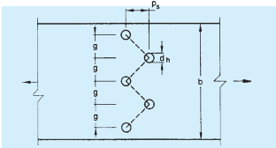
FIG. 5 PLATES WITH BOLTS HOLES IN TENSION
12.3.2 Threaded Rods
The design strength of threaded rods in tension, , as governed by rupture is given by:
where
net root area at the threaded section.
12.3.3 Single Angles
The rupture strength of an angle connected through one leg is affected by shear lag. The design strength, , as governed by rupture at net section is given by:
where
where
outstand leg width,
shear lag width, as shown in Fig. 6, and
= length of the end connection, that is the distance between the outermost bolts in the end joint measured along the load direction or length of the weld along the load direction.
For preliminary sizing, the rupture strength of net section may be approximately taken as:
where
α = 0.6 for one or two bolts, 0.7 for three bolts and 0.8 for four or more bolts along the length in the end connection or equivalent weld length,
net area of the total cross-section,
net area of the connected leg,
gross area of the outstanding leg, and
= thickness of the leg.
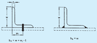
FIG. 6 ANGLES WITH SINGLE LEG CONNECTIONS
12.3.4 Other Section
The rupture strength, , of the double angles, channels, I-sections and other rolled steel sections, connected by one or more elements to an end gusset is also governed by shear lag effects. The design tensile strength of such sections as governed by tearing of net section may also be calculated using equation in 12.3.3, where is calculated based on the shear lag distance, , taken
PART 6 STRUCTURAL DESIGN — SECTION 6 STEEL
from the farthest edge of the outstanding leg to the nearest bolt/weld line in the connected leg of the cross-section.
12.4 Design Strength Due to Block Shear
The strength as governed by block shear at an end connection of plates and angles is calculated as given in 12.4.1.
12.4.1 Bolted Connections
The block shear strength, of connection shall be taken as the smaller of,
= ultimate and yield stress of the material, respectively.
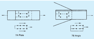
FIG. 7 BLOCK SHEAR FAILURE
12.4.2 Welded Connection
The block shear strength, shall be checked for welded end connections by taking an appropriate section in the member around the end weld, which can shear off as a block.