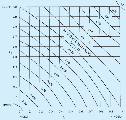
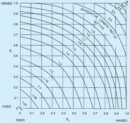
E-1 In the absence of more exact analysis, the effective length of columns in framed structures may be obtained from the ratio of effective length to unsupported length l given in Fig. 32 when relative displacement of the ends of the column is prevented and in Fig. 33 when relative lateral displacement of the ends is not prevented. In the latter case, it is recommended that the effective length ratio may not be taken to be less than 1.2.
(Clause 25.1.2) Ductile Design and Detailing of Reinforced Concrete Structures Subjected to Seismic Forces
F-1 General
F-1.1 This annex covers the requirements for designing and detailing of members of reinforced concrete (RC) structures designed to resist lateral effects of earthquake shaking, so as to give them adequate stiffness, strength and ductility to resist severe earthquake shaking without collapse. This annex addresses lateral load resisting structural systems of RC structures composed of,
a) RC moment resisting frames;
b) RC moment resisting frames with unreinforced masonry infill walls;
c) RC moment resisting frames with RC structural walls; and
d) RC structural walls.
F-1.2 Provisions of this annex shall be adopted in all lateral load resisting systems of RC structures located in Seismic Zone III, IV or V. The annex is optional in Seismic Zone II.
F-1.3 The provisions for RC structures given herein apply specifically to monolithic RC construction, and not for precast RC structures. Precast and/or prestressed concrete members may be used, only if they are designed to provide similar level of ductility as that of monolithic RC structures during or after an earthquake. Likewise, flat slab structures shall have a lateral load resisting system capable of providing similar level of performance as envisioned in this Section and shall be designed for drift compatibility as per F-10. Specialist literature shall be referred to for design and construction of such structures. The adequacy of such designs shall be demonstrated by adequate, appropriate experimentation and non-linear dynamic structural analyses.
F-1.4 All RC frames, RC walls and their elements in a structure need not be designed to resist lateral loads and the designer can judiciously identify the lateral load resisting system based on relative stiffness and location in the building and design those members for full lateral force. RC monolithic members assumed not to participate in the lateral force resisting system (see F-2.7) shall be permitted provided that their effect on the seismic response of the system is accounted for. Consequence of failure of structural and non-structural members not part of the lateral force resisting system shall also be considered in design.
F-2 Terminology
For the purpose of this annex, the following definitions shall apply.
F-2.1 Beams — These are members (generally horizontal) of moment resisting frames with flexural and shearing actions.
F-2.2 Boundary Elements — These are portions along the ends of a structural wall that are strengthened by longitudinal and transverse reinforcement. They may have the same thickness as that of the wall web.
F-2.3 Columns — These are members (generally vertical) of moment resisting frames with axial, flexural and shearing actions.
F-2.4 Cover Concrete — It is that concrete which is not confined by transverse reinforcement.
F-2.5 Transverse Reinforcement — It is a continuous bar having a 135∘ hook with an extension of 6 times diameter (but not < 65 mm) at one end and a hook not less than 90∘ with an extension of 6 times diameter (but not < 65 mm) at the other end. The hooks shall engage peripheral longitudinal bars. In general, the hooks of two successive crossties engaging the same longitudinal bars shall be alternated end for end. Transverse reinforcement (also called hoops) in columns is typically called stirrups and that in beams is called cross-ties.
F-3 Symbols
For the purpose of this annex, the following letter symbols shall have the meaning indicated against each; where other symbols are used, they are explained at the appropriate place. All dimensions in millimetre, loads in Newton and stresses in MPa, unless otherwise specified.
Ae = Effective cross-sectional area of a joint
Aej = Effective shear area of a joint
= Gross cross-sectional area of column, wall
= Horizontal reinforcement area within spacing
= Area of concrete core of column
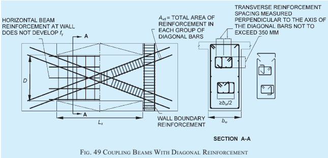
= Reinforcement along each diagonal of coupling beam
= Area of cross-section of bar forming spiral or link
= Area of uniformly distributed vertical reinforcement
= Vertical reinforcement at a joint
= Width of beam
= Width of column
= Effective width of a joint
D = Overall depth of beam
= Diameter of column core measured to the outside of spiral or link
d = Effective depth of member
= Diameter of longitudinal bar
= Effective depth of wall section
F-4 General Specifications
F-4.1 The design and construction of reinforced concrete buildings shall be governed by provisions of this Subsection 5A, except as modified by the
provisions of this annex for those elements participating in lateral force resistance.
F-4.2 Minimum grade of structural concrete shall be M 20, but M 25 for buildings,
a) more than 15m in height in Seismic Zones III, IV and V; and
b) but not less than that required by provisions of Subsection 5A based on exposure conditions.
F-4.3 Steel reinforcement resisting earthquake-induced forces in RC frame members and in boundary elements of RC structural walls shall comply with F-4.3.1 to F-4.3.3.
F-4.3.1 Steel reinforcements used shall be,
a) of grade Fe 415 or less {conforming to accepted standard [6-5A(36)]}; and
b) of grade Fe 500 and Fe 550, that is; high strength deformed steel bars produced by thermo-mechanical treatment process having elongation more than 14.5 percent, and conforming to accepted standard [6-5A(36)].
F-4.3.2 The actual 0.2 percent proof strength of steel bars based on tensile test shall not exceed their characteristic 0.2 percent proof strength by more than 20 percent.
F-4.3.3 The ratio of the actual ultimate strength to the actual 0.2 percent proof strength shall be at least 1.15.
F-4.4 In RC frame buildings, lintel beams shall preferably not be integrated into the columns to avoid short column effect. When integrated, they shall be included in the analytical model for structural analysis. Similarly, plinth beams (where provided), and staircase beams and slabs framing into columns shall be included in the analytical model for structural analysis.
F-4.5 RC regular moment-resisting frame buildings shall have planar frames oriented along the two principal plan directions of buildings. Irregularities listed under 5 of Part 6 ‘Structural Design, Section 1 Loads, Forces and Effects’ of the Code shall be avoided. Buildings with any of the listed irregularities perform poorly during earthquake shaking; in addition, buildings with floating columns and set-back columns also perform poorly. When any such irregularities are adopted, detailed nonlinear analyses shall be performed to demonstrate that there is no threat to loss of life and property.
F-5.1 General
Requirements of this section shall apply to beams resisting earthquake-induced effects, in which the
PART 6 STRUCTURAL DESIGN — SECTION 5 CONCRETE: 5A PLAIN AND REINFORCED CONCRETE
factored axial compressive stress does not exceed 0.08fck . Beams, in which the factored axial compressive stress exceeds 0.08fc , shall be designed as per requirements of F-6.
F-5.2 Longitudinal Reinforcement
F-5.2.1 The longitudinal reinforcement in beams shall be as below:
a) Beams shall have at least two 12 mm diameter bars each at the top and bottom faces.
b) Minimum longitudinal steel ratio ρmin required on any face at any section is:
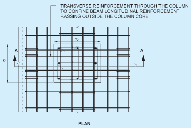
34A PLAN VIEW OF A BEAM COLUMN JOINT SHOWING EFFECTIVE BREADTH AND WIDTH OF JOINT
34B MAXIMUM EFFECTIVE WIDTH OF WIDE BEAM AND REQUIRED TRANSVERSE REINFORCEMENT
FIG. 34 BEAM COLUMN JUNCTIONS
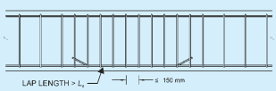
F-5.2.6.1 Lap splices
When adopted, closed links shall be provided over the entire length over which the longitudinal bars are spliced. Further,
a) the spacing of these links shall not exceed 150 mm (see Fig. 36).
b) the lap length shall not be less than the development length of the largest longitudinal reinforcement bar in tension.
c) lap splices shall not be provided,
within a joint ;
within a distance of 2d from face of the column; and
within a quarter length of the beam adjoining the location where flexural yielding may occur under earthquake effects.
d) not more than 50 percent of area of steel bars on either top or bottom face shall be spliced at any one section.
FIG. 36 LAP LENGTH AT LOCATION OF SPLICING OF LONGITUDINAL BARS IN BEAM
F-5.2.6.2 Mechanical couplers
Mechanical couplers {conforming to accepted standard [6-5A(38)]} shall be used when longitudinal steel bars have to be continued for beam spans larger than their manufacture lengths. Further,
a) only those mechanical splices conforming to the above code and capable of developing the specified tensile strength of spliced bar shall be permitted within a distance equal to two times the depth of the member from the member face or in any location where yielding of reinforcement is likely to take place; and
b) the spacing between adjacent longitudinal bars shall be based also on the outer size of the coupler to allow easy flow of concrete.
F-5.2.6.3 Welded splices
Welded splices shall not be used in beams for a distance equal to two times the depth of the member from the member face or in any location where yielding of reinforcement is likely to take place. At any location, not more than 50 percent of area of steel bars shall be spliced at any one section.
Welding of links, ties, inserts or other similar elements to vertical reinforcement bars required as per design is not permitted, in any seismic zone.
F-5.3 Transverse Reinforcement
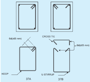
F-5.3.1 Only vertical links shall be used in beams (see Fig. 37A); inclined links shall not be used; and,
a) in normal practice, a link is made of a single
PART 6 STRUCTURAL DESIGN — SECTION 5 CONCRETE: 5A PLAIN AND REINFORCED CONCRETE
bent bar. But, it may be made of two bars also, namely a U-link with a 135∘ hook with an extension of 6 times diameter (but not less than 65 mm) at each end, embedded in the core concrete, and a cross-tie (see Fig. 37B).
b) the hooks of the links and cross-ties shall engage around peripheral longitudinal bars. Consecutive crossties engaging the same longitudinal bars shall have their 90∘ hooks at opposite sides of the beam. When the longitudinal reinforcement bars are secured by cross-ties in beams that have a slab on one side, the hooks of the cross-ties shall be placed on that side.
F-6.1 Geometry
Requirements of this section shall apply to columns and inclined members resisting earthquake-induced effects, in which the factored axial compressive stress due to gravity and earthquake effects exceeds 0.08fck . The factored axial compressive stress considering all load combinations relating to seismic loads shall be limited to 0.40fck in all such members, except in those covered in 10.
F-6.2 Relative Strengths of Beams and Columns at a Joint
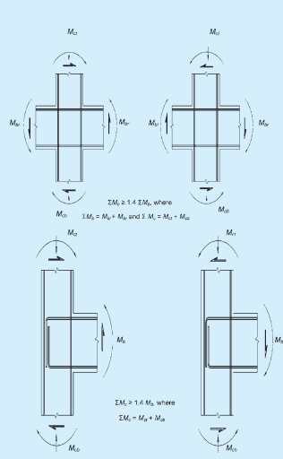
F-6.2.1 At each beam-column joint of a moment-resisting frame, the sum of nominal design strength of columns meeting at that joint (with nominal strength calculated for the factored axial load in the direction of the lateral force under consideration so as to give
FIG. 39 DETAILS OF TRANSVERSE REINFORCEMENT IN BEAMS
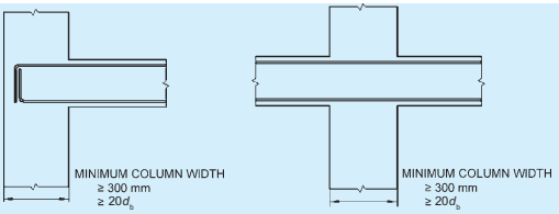
FIG. 40 MINIMUM SIZE OF RC COLUMNS BASED ON DIAMETER OF LARGEST LONGITUDINAL REINFORCEMENT BAR IN BEAMS FRAMING INTO IT
PART 6 STRUCTURAL DESIGN — SECTION 5 CONCRETE: 5A PLAIN AND REINFORCED CONCRETE
least column nominal design strength) along each principal plane shall be at least 1.4 times the sum of nominal design strength of beams meeting at that joint in the same plane (see Fig. 41).
In the event of a beam-column joint not conforming to above, the columns at the joint shall be considered to be gravity columns only and shall not be considered as part of the lateral load resisting system.
F-6.2.1.1 The design moments of resistance of a beam shall be estimated based on the principles of mechanics and the limiting strain states of the limit state design method enunciated in this Subsection 5A. The design moment of resistance of a column shall be estimated as in case of beams corresponding to zero axial force on the design P-M interaction diagram.
F-6.2.1.2 This check shall be performed at each joint for both positive and negative directions of shaking in the plane under consideration. Further, in this check, design moments of resistance in beam(s) meeting at a joint shall be considered in the same direction, and similarly the design moments of resistance of column(s) at the same joint shall be considered to be in the direction opposite to that of the moments in the beams.
F-6.2.1.3 This check shall be waived at all joints at roof level only, in buildings more than 4 storeys tall.
The provisions of F-6.2 are not applicable for flat slab structures.
F-6.3.2.1 Lap splices
When adopted, closed links shall be provided over the entire length over which the longitudinal bars are spliced. Further,
a) the spacing of these links shall not exceed 100mm.
b) the lap length shall not be less than the development length of the largest longitudinal reinforcement bar in tension.
c) lap splices shall be provided only in the central half of clear column height, and not
within a joint, or
within a distance of 2d from face of the beam.
d) not more than 50 percent of area of steel bars shall be spliced at any one section.
e) lap splices shall not be used for bars of diameter larger than 32 mm for which mechanical splicing shall be adopted,
F-6.3.2.2 Mechanical couplers
Mechanical couplers {see accepted standard [6-5A(38)]} shall be used. Further, only those mechanical splices conforming to the above standard and capable of developing the specified tensile strength of spliced bar shall be permitted within a distance equal to two times the depth of the member from the column face in any location where yielding of reinforcement is likely to take place.
F-6.3.2.3 Welded splices
Welded splices shall not be used in columns for a distance equal to two times the depth of the member from the member face or in any location where yielding of reinforcement is likely to take place. At any location, not more than 50 percent of area of steel bars shall be spliced at any one section. But, welding of links, ties, inserts or other similar elements to vertical reinforcement bars required as per design is not permitted, in any seismic zone.
FIG. 41 STRONG COLUMN - WEAK BEAM
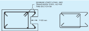
F-6.3.3 A column that extends more than 100 mm beyond the confined core owing to architectural requirement (see Fig. 42) shall be detailed in the following manner:
a) When the contribution of this area is considered in the estimate of strength of columns, it shall have at least the minimum longitudinal and transverse reinforcement given in this Subsection 5A.
b) When the contribution of this area is not considered in the estimate of strength of columns, it shall have at least the minimum longitudinal and transverse reinforcement given in this Subsection 5A.
F-6.4 Transverse Reinforcement
F-6.4.1 Transverse reinforcement shall consist of closed loop,
a) spiral or circular links in circular columns, and
b) rectangular links in rectangular columns.
In either case, the closed link shall have 135∘ hook ends with an extension of 6 times its diameter (but not < 65 mm) at each end, which are embedded in the confined core of the column (see Fig. 43A).
F-6.4.2 When rectangular links are used,
a) the minimum diameter permitted of transverse reinforcement bars is 8 mm, when diameter of longitudinal bar is less than or equal to 32 mm, and 10 mm, when diameter of longitudinal bar is more than 32 mm;
b) the maximum spacing of parallel legs of links shall be 300 mm centre-to-centre;
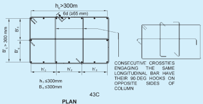
c) a cross-tie shall be provided, if the length of any side of the link exceeds 300 mm (see Fig. 43B); the cross-tie shall be placed perpendicular to this link whose length exceeds 300 mm. Alternatively, a pair of overlapping links may be provided within the column (see Fig. 43C). In either case, the hook ends of the links and cross-ties shall engage around peripheral longitudinal bars. Consecutive cross-ties engaging the same longitudinal bars shall have their 90° hooks
FIG. 42 REINFORCEMENT REQUIREMENT IN COLUMNS WITH PROJECTION MORE THAN 100 mm BEYOND CORE
on opposite sides of the column. Crossties of the same or smaller bar size as the hoops shall be permitted; and,
d) the maximum spacing of links shall be half the least lateral dimension of the column, except where special confining reinforcement is provided as per F-7.
F-6.5 Design Shear Force in Columns
The design shear force demand on columns is the larger of,
a) factored shear force demand as per linear structural analysis; and
b) factored equilibrium shear force demand when plastic hinges are formed at both ends of the beams given by:
For sway to right:
Vu=1.4
F-8.1.2 Design Shear Stress Demand on a Joint
a) Design shear stress demand acting horizontally along each of the two principal plan directions of the joint shall be estimated from earthquake shaking considered along each of these directions, using,
FIG. 48 PLAN VIEW OF A BEAM COLUMN JOINT SHOWING EFFECTIVE BREADTH AND WIDTH OF JOINT
τjdX= for shaking along plan direction X of earthquake shaking,
F-8.2 Transverse Reinforcement
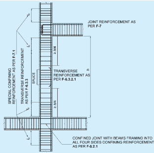
F-8.2.1 Confining Reinforcement in Joints
a) When all four vertical faces of the joint are having beams framing into them covering at least 75 percent of the width on each face,
At least half the special confining reinforcement required as per F-7 at the two ends of columns, shall be provided through the joint within the depth of the shallowest beam framing into it; and
Spacing of these transverse links shall not exceed 150 mm.
b) When all four vertical faces of the joint are not having beams framing into them or when all four vertical faces have beams framing into them but do not cover at least 75 percent of the width on any face,
special confining reinforcement required as per F-7 at the two ends of columns shall be provided through the joint within the depth of the shallowest beam framing into it, and
spacing of these transverse links shall not exceed 150 mm.
F-8.2.2 In the exterior and corner joints, all 135∘ hooks of cross-ties should be along the outer face of columns.
F-9 Special Shear Walls
F-9.1 General Requirements
F-9.1.1 The requirements of this clause apply to special shear walls that are part of lateral force resisting system of earthquake-resistant RC buildings.
F-9.1.2 The minimum thickness of special shear walls shall not be less than,
a) 150mm; and
b) 300 mm for buildings with coupled shear walls in any seismic zone.
The minimum thickness provided shall conform to the fire resistance requirements based on occupancy as laid down in this Subsection 5A.
F-9.1.3 The minimum ratio of length of wall to its thickness shall be 4.
F-9.1.4 Special shear walls shall be classified as squat, intermediate or slender depending on the overall height hw to Length ratio as:
F-9.2 Design for Shear Force
F-9.2.1 Nominal shear stress demand τv on a wall shall be estimated as:
τv
F-9.3 Design for Axial Force and Bending Moment
F-9.3.1 Design moment of resistance Mu of the wall section subjected to combined bending moment and compressive axial load shall be estimated in accordance with requirements of limit state design method given in this Subsection 5A, using the principles of mechanics involving equilibrium equations, strain compatibility conditions and constitutive laws.
The moment of resistance of slender rectangular structural wall section with uniformly distributed vertical reinforcement may be estimated using expressions given in F-9.9. Expressions given in F-9.9 are not applicable for structural walls with boundary elements,
F-9.3.2 The cracked flexural strength of a wall section shall be greater than its uncracked flexural strength.
F-9.3.3 In structural walls that do not have boundary elements, at least a minimum of 4 bars of 12mm diameter arranged in 2 layers, shall be concentrated as vertical reinforcement at the ends of the wall over a length not exceeding twice the thickness of RC wall.
F-9.4 Boundary Elements
Boundary elements are portions along the wall edges that are strengthened by longitudinal and transverse reinforcement even if they have the same thickness as that of the wall web. It is advantageous to provide boundary elements with dimension greater than thickness of the wall web.
F-9.4.1 Boundary elements shall be provided along the vertical boundaries of walls, when the extreme fibre compressive stress in the wall exceeds 0.2fck due to factored gravity loads plus factored earthquake force. Boundary elements may be discontinued at elevations where extreme fibre compressive stress becomes less than 0.15f. Extreme fibre compressive stress shall be estimated using a linearly elastic model and gross section properties.
F-9.5 Coupling Beams
F-9.5.1 Coplanar special structural walls may be connected by means of coupling beams.
F-9.5.2 If earthquake induced shear stress τve in coupling beam exceeds,
τ
F-9.6 Openings in Walls
F-9.6.1 Shear strength of a wall with openings should be checked at critical horizontal planes passing through openings.
F-9.6.2 Additional steel reinforcement shall be provided along all four edges of openings in walls. Further,
a) the area of these vertical and horizontal steel should be equal to that of the respective interrupted bars, provided half on either side of the wall in each direction.
b) these vertical bars should extend for full height of the storey in which this opening is present.
PART 6 STRUCTURAL DESIGN — SECTION 5 CONCRETE: 5A PLAIN AND REINFORCED CONCRETE
c) the horizontal bars should be provided with development length in tension beyond the edge of the opening.
F-9.7 Construction Joints
Vertical reinforcement across a horizontal construction joint shall have area, Ast is given by:
F-9.8.3.1 Lap splices
When adopted, closed links shall be provided over the entire length over which the longitudinal bars are spliced. Further,
a) the spacing of these links shall not exceed 150mm.
b) the lap length shall not be less than the development length of the largest longitudinal reinforcement bar in tension.
c) lap splices shall be provided only in the central half of clear wall height, and not,
within a joint; or
within a distance of 2d from a location where yielding of reinforcement is likely to take place.
d) not more than 50 percent of area of steel bars shall be spliced at any one section.
F-9.8.3.2 Mechanical couplers {conforming to accepted standard [6-5A(38)]} shall be used. Further, only those mechanical splices conforming to the above standard and capable of developing the specified tensile strength of spliced bar shall be permitted within a
distance equal to two times the depth of the member from the beam-column joint or in any location where yielding of reinforcement is likely to take place
F-9.8.3.3 Welded splices
Welded splices shall be avoided as far as possible. In no case shall they be used for a distance equal to two times the depth of the member from the member face or in any location where yielding of reinforcement is likely to take place. At any location, not more than 50 percent of area of steel bars shall be spliced at any one section.
Welding of links, ties, inserts or other similar elements to vertical reinforcement bars required as per design is not permitted, in any seismic zone.
F-9.8.4 In buildings located in Seismic Zones II and III, closed loop transverse links shall be provided around lapped spliced bars larger than 16 mm in diameter. The minimum diameter of such links shall be 1/4th of diameter of spliced bar but not less than 8 mm at spacing not exceeding 150 mm centres.
F-9.9 Moment of Resistance of Rectangular Shear Wall Section
The moment of resistance Mu of a slender rectangular structural wall section with uniformly distributed vertical reinforcement may be estimated as:
a)For
ef
/
l
lef/l
NOTES
1 Figures 31 and 32 are reproduced from ‘The Structural Engineer’ No. 7, Volume 52, July 1974 by the permission of the Council of the Institution of Structural Engineers, U.K.
2 In Figs. 31 and 32, β1 and β2 are equal to:
∑Kc+∑Kb∑Kc
where the summation is to be done for the members framing into a joint at top and bottom respectively; and Kc and Kb being the flexural stiffness for column and beam, respectively.
E-2 To determine whether a column is a no sway or a
sway column, stability index Q may be computed as given below:
Q=Huhs∑PuΔu
where
∑Pu= sum of axial loads on all column in the storey,
Δu= elastically computed first order lateral deflection,
Hu= total lateral force acting within the storey, and
hs= height of the storey.
If Q≤0.04, then the column in the frame may be taken as no sway column, otherwise the column will be considered as sway column.
E-3 For normal usage assuming idealized conditions, the effective length lef of the compression member in a given plane may be assessed on the basis of Table 32.
FIG. 32 EFFECTIVE LENGTH RATIOS FOR A COLUMN IN A FRAME WITH No SWAY
FIG. 33 EFFECTIVE LENGTH RATIOS FOR A COLUMN IN A FRAME WITHOUT RESTRAINT AGAINST SWAY
PART 6 STRUCTURAL DESIGN — SECTION 5 CONCRETE: 5A PLAIN AND REINFORCED CONCRETE
Table 32Effective Length of Compression Members (Clause E-3)
Sl No.(1)
Degree of End Restraint of Compression Members(2)
Symbol(3)
Theoretical Value of Effective Length(4)
Recommended Value of Effective Length(5)
i)
Effectively held in position and restrained against rotation at both ends
0.50 l
0.65 l
ii)
Effectively held in position at both ends, restrained against rotation at one end
0.70 l
0.80 l
iii)
Effectively held in position at both ends, but not restrained against rotation
1.00 l
1.00 l
iv)
Effectively held in position and restrained against rotation at one end, and at the other restrained against rotation but not held in position
1.00 l
1.20 l
v)
Effectively held in position and restrained against rotation at one end, and at the other partially restrained against rotation but not held in position
-
1.50 l
vi)
Effectively held in position at one end but not restrained against rotation, and at the other end restrained against rotation but not held in position
2.00 l
2.00 l
vii)
Effectively held in position and restrained against rotation at one end but not held in position nor restrained against rotation at the other end
2.00 l
2.00 l
NOTE - l is the unsupported length of compression member.
90∘
F-2.6 Gravity Columns in Buildings — It is a column, which is not part of the lateral load resisting system and designed only for force actions (that is, axial force, shear force and bending moments) due to gravity loads. But, it should be able to resist the gravity loads at lateral displacement imposed by the earthquake forces.
F-2.7 Lateral Force Resisting System — It is that part of the structural system which participates in resisting forces induced by earthquake.
F-2.8 Moment-Resisting Frame — It is a three-dimensional structural system composed of interconnected members, without structural walls, so as to function as a complete self-contained unit with or without the aid of horizontal diaphragms or floor bracing systems, in which the members resist gravity and lateral forces primarily by flexural actions.
PART 6 STRUCTURAL DESIGN — SECTION 5 CONCRETE: 5A PLAIN AND REINFORCED CONCRETE
F-2.8.1 Special Moment Resisting Frame (SMRF) — It is a moment-resisting frame specially detailed to provide ductile behaviour as per the requirements specified in F-4, F-5, F-6 and F-7.
F-2.8.2 Ordinary Moment Resisting Frame (OMRF) — It is a moment-resisting frame not meeting special detailing requirements for ductile behaviour.
F-2.9 Link — It is a single steel bar bent into a closed loop having a 135∘ hook with an extension of 6 times diameter (but not < 65 mm) at each end, which is embedded in the confined core of the section, and placed normal to the longitudinal axis of the RC beam or column.
F-2.10 Shear Wall (also called Structural Wall) — It is a vertically oriented planar element that is primarily designed to resist lateral force effects (axial force, shear force and bending moment) in its own plane.
F-2.11 Special Shear Wall — It is a structural wall meeting special detailing requirements for ductile behaviour specified in F-9.
Ag
Ah
sv
Ak
Asd
Ash
Ast
Av
bb
bc
bj
Dk
db
dw
Es= Elastic modulus of steel
fck=Characteristic compressive strength of concrete cube, in MPa
fy= Yield stress of steel reinforcing bars, or 0.2 percent proof strength of reinforcing steel, in MPa
h = Longer dimension of rectangular confining link measured to its outer face
hc
hj= Effective depth of a joint
hst
hw= Overall height of RC structural wall
LAB
Ld
lo= Length of member over which special confining reinforcement is to be provided
Lw= Horizontal length of wall/longer cross-section dimension of wall
Ls= Clear span of couplings beam
Mu= Design moment of resistance of entire RC beam, column or wall section
Mc1=Design moment of resistance of column section
Mc2=Design moment of resistance of column section
Mg1=Design moment of resistance of beam section
Mg2=Design moment of resistance of beam section
MuAh=Hogging design moment of resistance of beam at end A
MuAs=Sagging design moment of resistance of beam at end A
MuBh = Hogging design moment of resistance of beam at end B
MuBs=Sagging design moment of resistance of beam at end B
MuBL=Design moment of resistance of beam framing into column from the left
MuBR = Design moment of resistance of beam framing into column from the right
Muw= Design moment of resistance of web of RC structural wall alone
Pu= Factored axial load
sv= Spacing of links along the longitudinal direction of beam or column
tw= Thickness of web of RC structural wall
Vu,aD+L= Factored shear force demand at end A of beam due to dead and live loads
Vu,bD+L= Factored shear force demand at end B of beam due to dead and live loads
Vj= Design shear resistance of a joint
Vu= Factored shear force
Vus= Design shear resistance offered at a section by steel links
xuxu∗= Depth of neutral axis from extreme compression fibre
α= Inclination of diagonal reinforcement in coupling beam
ρ= Area of longitudinal reinforcement as a fraction of gross area of cross-section in a RC beam, column or structural wall
ρc= Area of longitudinal reinforcement on the compression face of a beam as a fraction of gross area of cross-section
(ρh)min= Minimum area of horizontal reinforcement of a structural wall as a fraction of gross area of cross-section
(ρv,be)min= Minimum area of vertical reinforcement in each boundary element of a structural wall as a fraction of gross area of cross-section of each boundary element
(ρv,net)min= Minimum area of vertical reinforcement of a structural wall as a fraction of gross area of cross-section of the wall
(ρv,web)min= Minimum area of vertical reinforcement in web of a structural wall as a fraction of gross area of cross-section of web
ρmax=Maximum area of longitudinal reinforcement permitted on the tension face of a beam as a fraction of gross area of cross-section
ρmin= Minimum area of longitudinal reinforcement to be ensured on the tension face of a beam as a fraction of gross area of cross-section
τc=Designshearstrengthofconcrete
τc,max=Maximum nominal shear stress permitted at a section of RC beam, column or structural wall
τv= Nominal shear stress at a section of RC beam, column or structural wall
F-5 Beams
k
F-5.1.1 Beams shall preferably have width-to-depth ratio of more than 0.3.
F-5.1.2 Beams shall not have width less than 200mm.
F-5.1.3 Beams shall not have depth D more than 1/4th of clear span. This may not apply to the floor beam of frame staging of elevated RC water tanks.
F-5.1.4 Width of beam bw shall not exceed the width of supporting member c2 plus distance on either side of supporting member equal to the smaller of (a) and (b) below:
a) Width of supporting member c2.
b) 0.75 times breadth of supporting member c1 (see Fig. 34A and Fig. 34B).
Transverse reinforcement for the width of a beam that exceeds width of the column c2 shall be provided as shown in Fig. 34B throughout the beam span including within the beam column joint.
ρ
min
=
0.24fyfck
F-5.2.2 Maximum longitudinal steel ratio ρmax provided on any face at any section is 0.025.
F-5.2.3 Longitudinal steel on bottom face of a beam framing into a column (at the face of the column) shall be at least half the steel on its top face at the same section. At exterior joints, the anchorage length calculation shall consider this bottom steel to be tension steel.
F-5.2.4 Longitudinal steel in beams at any section on top or bottom face shall be at least 1/4th of longitudinal steel provided at the top face of the beam at the face of the column; when the top longitudinal steel in the beam at the two supporting column faces is different, the larger of the two shall be considered.
F-5.2.5 At an exterior joint, top and bottom bars of beams shall be provided with anchorage length beyond the inner face of the column, equal to development length of the bar in tension plus 10 times bar diameter minus the allowance for 90∘ bends (see Fig. 35).
FIG. 35 ANCHORAGE OF LONGITUDINAL BEAM BARS AT EXTERIOR BEAM-COLUMN JOINT
F-5.2.6 Splicing of Longitudinal Bars
90∘
FIG. 37 DETAILS OF TRANSVERSE REINFORCEMENT IN BEAMS
F-5.3.2 The minimum diameter of a link shall be 8mm.
F-5.3.3 Shear force capacity of a beam shall be more than larger of,
a) factored shear force as per linear structural analysis; and
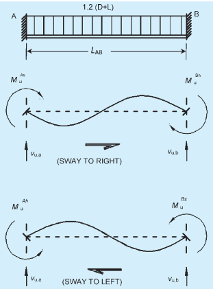
b) factored gravity shear force, plus equilibrium shear force when plastic hinges are formed at both ends of the beam (see Fig. 38) given by : 1) For sway to right:
Vu,a=Vu,aD+L−1.4LABMuAs+MuBh
Vu,b=Vu,bD+L+1.4LABMuAs+MuBh
For sway to left:
Vu,a=Vu,aD+L−1.4LABMuAh+MuBs
Vu,b=Vu,bD+L+1.4LABMuAh+MuBs
where MuAs , MuAh , MuBs and MuBh are sagging and hogging moments of resistance of the beam section at ends A and B, respectively. These shall be calculated as per this Subsection 5A. LAB is clear span of the beam. Vu,aD+L and Vu,bD+L are the factored shear forces at ends A and B, respectively, due to vertical loads acting on the span; the partial safety factor for dead and live loads shall be 1.2, and the beam shall be considered to be simply supported for this estimation.
The design shear force demand at end A of the beam shall be the larger of the two values of Vu,a computed above. Similarly, the design shear force demand at end B shall be the larger of the two values of Vu,b computed above.
FIG. 38 CALCULATION OF DESIGN SHEAR FORCE DEMAND ON BEAMS UNDER PLASTIC HINGE ACTION AT THEIR ENDS
F-5.3.4 In the calculation of design shear force capacity of RC beams, contributions of the following shall not be considered:
a) Bent up bars,
b) Inclined links, and
c) Concrete in the RC section.
F-5.3.5 Close Spacing of Links
Spacing of links over a length of 2d at either end of a beam shall not exceed,
a) d/4;
b) 8 times the diameter of the smallest longitudinal bar; and
c) 100 mm (see Fig. 39).
F-5.3.5.1 The first link shall be at a distance not exceeding 50 mm from the joint face.
F-5.3.5.2 Closely spaced links shall be provided over a length equal to 2d on either side of a section where flexural yielding may occur under earthquake effects. Over the remaining length of the beam, vertical links shall be provided at a spacing not exceeding d/2.
F-6 Columns and Inclined Members
For various shapes of columns other than rectangular and circular like ‘T’ shaped, ‘X’ shaped, etc. Appropriate designs and detailing shall be carried out using specialist literature where such columns are part of lateral load resisting systems.
F-6.1.1 The minimum dimension of a column shall not be less than,
a) 20db , where db is diameter of the largest diameter longitudinal reinforcement bar in the beam passing through or anchoring into the column at the joint, or
b) 300 mm (see Fig. 40).
F-6.1.2 The cross-section aspect ratio (that is, ratio of smaller dimension to larger dimension of the cross-section of a column or inclined member) shall not be less than 0.45. Vertical members of RC buildings whose cross-section aspect ratio is less than 0.4 shall be designed as per requirements of F-8.
F-6.3 Longitudinal Reinforcement
F-6.3.1 Circular columns shall have minimum of 6 bars.
F-6.3.2 Splicing of Longitudinal Bars
hst
(MuAs+MuBh)
,
For sway to left:
Vu=1.4hst(MuAh+MuBs),
where MuAs,MuAh,MuBs and MuBh are design sagging and hogging moments of resistance of beams framing into the column on opposite faces A and B, respectively, with one hogging moment and the other sagging (see Fig. 44); and hst the storey height. The design moments of resistance of beam sections shall be calculated as per this Subsection 5A.
F-6.5.1 The calculation of design shear force capacity of RC columns shall be calculated as per this Subsection 5A.
F-7 SPECIAL CONFINING REINFORCEMENT
The requirements of this section shall be met with in beams and columns, unless a larger amount of transverse reinforcement is required from shear strength considerations given in F-5.3.3 for beams and F-6.5 for columns.
F-7.1 Flexural yielding is likely in beams during strong earthquake shaking and in columns when the shaking intensity exceeds the expected intensity of earthquake shaking (see Fig. 45). This special confining reinforcement shall,
a) be provided over a length lo from the face of the joint towards mid-span of beams and mid heights of columns, on either side of the joint; where lo is not less than,
larger lateral dimension of the member at the section where yielding occurs,
1/6 of clear span of the member; or
PART 6 STRUCTURAL DESIGN — SECTION 5 CONCRETE: 5A PLAIN AND REINFORCED CONCRETE
FIG. 43 DETAIL OF TRANSVERSE REINFORCEMENT IN COLUMNS
FIG. 44 EQUILIBRIUM DESIGN SHEAR FORCE DEMAND ON COLUMN WHEN PLASTIC HINGES ARE FORMED AT BEAM ENDS
450 mm.
b) have a spacing not more than,
1/4 of minimum member dimension of the beam or column;
6 times diameter of the smallest longitudinal reinforcement bars; and
100mm link.
c) have area Ash of cross-section of the bar forming links or spiral of at least:
in circular links or spirals:
Ash= Maximum of
{0.09svDkfyfck(AkAg−1)and0.024svDkfyf
where
sv= pitch of spiral or spacing of links,
Dk = diameter of core of circular column measured to outside of spiral/link,
fck = characteristic compressive strength of concrete cube,
fy=0.2 percent proof strength of transverse steel reinforcement bars,
Ag = gross area of column cross-section, and
Ak= area of concrete core of column
=4πDk2
in rectangular links:
Ash= Maximum of
[0.18svhfyfck(AkAg−1)0.05svhfyfck
where
h = longer dimension of rectangular link measured to its outer face, which does not exceed 300 mm (see Fig. 43B), and
Ak = area of confined concrete core in rectangular link measured to its outer dimensions.
h of the link could be reduced by introducing crossties (see Fig. 43C). In such cases, Ak shall be measured as overall core area, regardless of link arrangement. Hooks of crossties shall engage peripheral longitudinal bars.
F-7.2 When a column terminates into a footing or mat,
special confining reinforcement shall extend at least 300mm into the footing or mat (see Fig. 46).
FIG. 45 COLUMN AND JOINT DETAILING
FIG. 46 PROVISION OF SPECIAL CONFINING REINFORCEMENT IN FOOTING
F-7.3 When the calculated point of contra-flexure, under the effect of gravity and earthquake effects, is not within the middle half of the member clear height, special confining reinforcement shall be provided over the full height of the column.
F-7.4 Special confining reinforcement shall be provided over the full height of a column which has significant variation in stiffness along its height. This variation in stiffness may result due to abrupt changes in cross-section size, or unintended restraint to the column provided by stair-slab, mezzanine floor, plinth or lintel beams framing into the columns, RC wall or masonry wall adjoining column and extending only for partial column height.
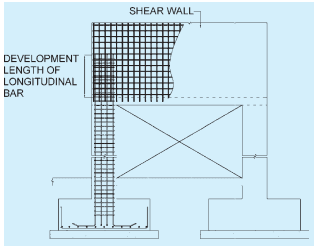
F-7.5 Columns supporting reactions from discontinued stiff members, such as walls, shall be provided with special confining reinforcement over their full height. (see Fig. 47). This reinforcement shall also be placed above the discontinuity for at least the development length of the largest longitudinal bar in the column.
PART 6 STRUCTURAL DESIGN — SECTION 5 CONCRETE: 5A PLAIN AND REINFORCED CONCRETE
Where the column is supported on a wall, this reinforcement shall be provided over the full height of the column; it shall also be provided below the discontinuity for the same development length.
FIG. 47 COLUMNS WITH VARIABLE STIFFNESS
F-8 BEAM-COLUMN JOINTS OF MOMENT-RESISTING FRAMES
F-8.1 Design of Beam-Column Joint for Distortional Shear
F-8.1.1 Shear Strength of Concrete in a Joint
The nominal shear strength τjc of concrete in a beam-column joint shall be taken as:
τjc=⎩⎨⎧1.51.21.0Aej
where Aej is effective shear area of joint given by bjwj , in which bj is the effective breadth of joint perpendicular to the direction of shear force and wj the effective width of joint along the direction of shear force. The effective width of joint bj (see Fig. 48) shall be obtained from following:
min[bb;bc+0.5hc] if bc<bb
where
bb= width of beam. bc= width of column.
hc= Depth of column in considered direction.
bjwj
VdjX
τjdY=bjwjVdjY for shaking along plan direction Y of earthquake shaking
It shall be ensured that the joint shear capacity of joint concrete estimated using F-8.1.1 exceeds both τjdX and τjdY.
b) Design shear force demands VjdX and VjdY acting horizontally on the joint in principal plan directions X and Y shall be estimated considering that the longitudinal beam bars in tension reach a stress of 1.25fy (when over strength plastic moment hinges are formed at beam ends).
F-8.1.3 Width of Beam Column Joint
When beam reinforcement extends through beam-column joint, the minimum width of the column parallel to beam shall be 20 times the diameter of the largest longitudinal beam bar.
Lw
a) Squat walls: hw/Lw<1 ,
b) Intermediate walls: 1≤hw/Lw≤2, and
d) Slender walls: hw/Lw>2
F-9.1.5 In the design of flanged wall sections, only that part of the flange shall be considered which extends beyond the face of the web of the structural wall at least for a distance equal to smaller of,
a) actual width available;
b) half the distance to the adjacent structural wall web; and
c) 1/10th of the total wall height.
F-9.1.6 Special shear walls shall be provided with uniformly spaced reinforcement in its cross-section along vertical and horizontal directions. At least a minimum area of reinforcement bars as indicated in Table 33 shall be provided along vertical and horizontal directions.
F-9.1.7 Reinforcement bars shall be provided in two curtains within the cross-section of the wall, with each curtain having bars running along vertical and horizontal directions, when,
a) factored shear stress demand in the wall exceeds 0.25fck MPa; or
b) wall thickness is 200 mm or higher.
When steel is provided in two layers, all vertical steel bars shall be contained within the horizontal steel bars; the horizontal bars shall form a closed core concrete area with closed loops and cross-ties.
F-9.1.8 The largest diameter of longitudinal steel bars used in any part of a wall shall not exceed 1/10th of the thickness of that part.
F-9.1.9 The maximum spacing of vertical or horizontal reinforcement shall not exceed smaller of,
a) 1/5th horizontal length Lw of wall;
b) 3 times thickness tw of web of wall; and
c) 450 mm.
F-9.1.10 Special shear walls shall be founded on properly designed foundations and shall not be discontinued to rest on beams, columns or inclined members.
PART 6 STRUCTURAL DESIGN — SECTION 5 CONCRETE: 5A PLAIN AND REINFORCED CONCRETE
Table 33 Minimum Reinforcement in RC Shear Walls(Clause F-9.1.6)
where, Vu is factored shear force, tw thickness of the web, and dw effective depth of wall section (along the length of the wall), which may be taken as 0.8Lw for rectangular sections.
F-9.2.2 Design shear strength τc of concrete shall be calculated as per Table 19.
F-9.2.3 When nominal shear stress demand τv on a wall is,
a) more than maximum design shear strength τc,max of concrete (given in Table 20), the wall section shall be re-designed;
b) less than maximum design shear strength τc,max of concrete and more than design shear strength τc of concrete, design horizontal shear reinforcement shall be provided of area Ah given by:
Ah=0.87fy(svd)IntegralVus=0.87fy(svd)
which shall not be less than the minimum area
of horizontal steel as per F-9.1.5; and
c) less than design shear strength τc of concrete, horizontal shear reinforcement shall be the minimum area of horizontal steel as per F-9.1.5.
ck
F-9.4.2 A boundary element shall have adequate axial load carrying capacity, assuming short column action, so as to enable it to carry axial compression arising from factored gravity load and lateral seismic shaking effects.
F-9.4.2.1 The load factor for gravity load shall be taken as 0.8, if gravity load gives higher axial compressive strength of the boundary element.
F-9.4.3 The vertical reinforcement in the boundary elements shall not be less than 0.8 percent and not greater than 6 percent; the practical upper limit would be 4 percent to avoid congestion.
F-9.4.4 Boundary elements, where required as per F-9.4.1, shall be provided with special confining reinforcement throughout their height, given by:
Ash=0.05svhfyfck
and have a spacing not more than,
a) 1/3 of minimum member dimension of the boundary element;
b) 6 times diameter of the smallest longitudinal reinforcement bars; and
c) 100 mm but may be relaxed to 150 mm if maximum distance between cross-ties/parallel legs of links or ties is limited to 200 mm, but need not be less than 100 mm.
F-9.4.5 Boundary elements need not be provided, if the entire wall section is provided with special confining reinforcement, as per F-7.
ve
>
0.1fck(DLs),
where Ls is clear span of coupling beam and D overall depth, the entire earthquake-induced shear, bending
moment and axial compression shall be resisted by diagonal reinforcement alone. Further,
a) area of this diagonal reinforcement along each diagonal shall be estimated as:
Asd=1.74fysinαVu,
where Vu is factored shear force on the coupling beam and α the angle made by diagonal reinforcement with the horizontal; and
b) at least 4 bars of 8 mm diameter shall be provided along each diagonal. All longitudinal bars along each diagonal shall be enclosed by special confining transverse reinforcement as per F-7 at a spacing not exceeding 100 mm.
F-9.5.3 The diagonal of a coupling beam shall be anchored in the adjacent walls with an anchorage length of 1.5 times the development length in tension (see Fig. 49).
AgAst≥fy0.92(τv−AgPu)
where τv is factored shear stress at the joint, Pu factored axial force (positive for compression), and Ag gross cross-sectional area of joint.
F-9.8 Development, Splice and Anchorage Requirement
F-9.8.1 Horizontal reinforcement shall be anchored near the edges of wall or in confined core of boundary elements.
F-9.8.2 In slender walls (H/Lw>2) , splicing of vertical flexural reinforcement should be avoided, as far as possible, in regions where flexural yielding may take place, which extends for a distance larger of,
a) Lw above the base of the wall; and
b) 1/6th of the wall height;
but not larger than 2Lw
F-9.8.3 Splices
(xu/Lw)
<
(xu∗/Lw)
fcktwLw2Mu=φ[(1+φλ)(21−0.416Lwxu)−
(Lwxu)2(0.168+3β2)]]
where
Lwxu=(2φ+0.36φ+λ);
Lwxu∗=0.0035+(0.002+0.87fy/Es)0.0035
φ=(fck0.87fyρ);
λ=fcktwLwPu
ρ=vertical reinforcement ratio=(twLwAst),
Ast = area of uniformly distributed vertical reinforcement,
β=0.0035(0.002+0.87fy/Es),
Es= elastic modulus of steel, and
Pu= factored compressive axial force on wall.
b) For (xu∗/Lw)<(xu/Lw)<1.0
fcktwLw2Mu=α1(Lwxu)−α2(Lwxu)α3−2λ∣
where
α1=[0.36+φ(1−2β−2β1)]
α2=[0.15+2φ(1−β+3β2−3β1)]and
α3=6βφ(xu/Lw1−3).
xu/Lw to be used in this expression shall be obtained by solving the equation:
α1(Lwxu)2+α4(Lwxu)−α5=0
where
α4=(βφ−λ),and
α5=(2βφ).
F-10 Gravity Columns in Buildings
Gravity columns in buildings shall be detailed according to F-10.1 and F-10.2 for bending moments induced when subjected to ‘R’ times the design lateral displacement under the factored equivalent static design seismic loads given by 5 of Part 6 ‘Structural Design, Section 1 Loads, Forces and Effects’ of the Code.
F-10.1 The provisions in F-10.1.1 and F-10.1.2 shall be satisfied, when induced bending moments and horizontal shear forces under the said lateral displacement combined with factored gravity bending moment and shear force do not exceed the design moment of resistance and design lateral shear capacity of the column.
F-10.1.1 Gravity columns shall satisfy F-6.3.2, F-6.4.1 and F-6.4.2. But, spacing of links along the full column height shall not exceed 6 times diameter of smallest longitudinal bar or 150mm.
F-10.1.2 Gravity columns with factored gravity axial stress exceeding 0.4fck shall satisfy F-10.1.1 and shall have transverse reinforcement at least one half of special confining reinforcement required by F-7.
F-10.2 When induced bending moments and shear forces under said lateral displacement combined with factored gravity bending moment and shear force exceed design moment and shear strength of the frame, F-10.2.1 and F-10.2.2 shall be satisfied.
F-10.2.1 Mechanical and welded splices shall satisfy F-6.3.2.2 and F-6.3.2.3.
F-10.2.2 Gravity columns shall satisfy F-6.4 and F-7.
PART 6 STRUCTURAL DESIGN — SECTION 5 CONCRETE: 5A PLAIN AND REINFORCED CONCRETE