Section 4 Masonry
1 SCOPE
1.1 This Code (Part 6/Section 4) covers the structural design aspects of unreinforced load bearing and non-load bearing walls, constructed with masonry units permitted in accordance with this section.
1.2 This Section also deals with the selection of materials, special features of design and construction for masonry construction using rectangular masonry units. It also covers guidelines regarding earthquake resistant buildings constructed using masonry of low strength.
1.3 This Section also covers provisions for design of reinforced brick and reinforced brick concrete floors and roofs.
1.4 This Section also gives the recommendations for structural design aspects of reinforced load bearing and non-load bearing walls, constructed with different types of bricks and blocks.
1.5 The recommendations of the Section do not apply to walls constructed in mud mortars.
2 TERMINOLOGY
For the purpose of this Section, the definitions given below shall apply.
2.1 Bed Block — A block bedded on a wall, column or pier to disperse a concentrated load on a masonry element.
2.2 Bond — Arrangement of masonry units in successive courses to tie the masonry together both longitudinally and transversely; the arrangement is usually worked out to ensure that no vertical joint of one course is exactly over the one in the next course above or below it, and there is maximum possible amount of lap.
2.3 Column, Pier and Buttress
a) Column — An isolated vertical load bearing member, width of which does not exceed four times the thickness.
b) Pier — A thickened section forming integral part of a wall placed at intervals along the wall, to increase the stiffness of the wall or to carry a vertical concentrated load. Thickness of a pier is the overall thickness including the thickness of the wall or, when bonded into a leaf of a cavity wall, the thickness obtained
by treating that leaf as an independent wall (see Fig. 1)
c) Buttress — A pier of masonry built as an integral part of wall and projecting from either or both surfaces, decreasing in cross-sectional area from base to top.
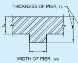
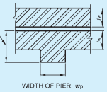
FIG.1 DEFINITION OF PIER
2.4 Cross-Sectional Area of Masonry Unit — Net cross-sectional area of a masonry unit shall be taken as the gross cross-sectional area minus the area of cellular space. Gross cross-sectional area of cored units shall be determined to the outside of the coring but cross-sectional area of grooves shall not be deducted from the gross cross-sectional area to obtain the net cross-sectional area.
2.5 Curtain Wall — A non-load bearing wall subject to lateral loads. It may be laterally supported by vertical or horizontal structural members, where necessary (see Fig. 2).
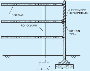
NOTE — The figure is only illustrative to explain about the term curtain wall and is not intended to be an exhaustive provision.
FIG. 2 TYPICAL MASONRY CURTAIN WALL
PART 6 STRUCTURAL DESIGN — SECTION 4 MASONRY
2.6 Effective Height — The height of a wall or column, to be considered for calculating slenderness ratio.
2.7 Effective Length — The length of a wall to be considered for calculating slenderness ratio.
2.8 Effective Thickness — The thickness of a wall or column to be considered for calculating slenderness ratio.
2.9 Hollow Unit — A masonry unit of which net cross-sectional area in any plane parallel to the bearing surface is less than 75 percent of its gross cross-sectional area measured in the same plane.
2.10 Grout — Mortar of pourable consistency.
2.21 Types of Walls
a) Cavity wall — A wall comprising two leaves,
each leaf being built of masonry units and separated by a cavity and tied together with metal ties or bonding units to ensure that the two leaves act as one structural unit, the space between the leaves being either left as continuous cavity or filled with a non-load bearing insulating and water-proofing material.
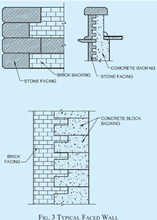
b) Faced wall — A wall in which facing and backing of two different materials are bonded together to ensure common action under load (see Fig. 3).
NOTE — To ensure monolithic action in faced walls, shear strength between the facing and the backing shall be provided by toothing, bonding or other means.
c) Veneered wall — A wall in which the facing is attached to the backing but not so bonded as to result in a common action under load.
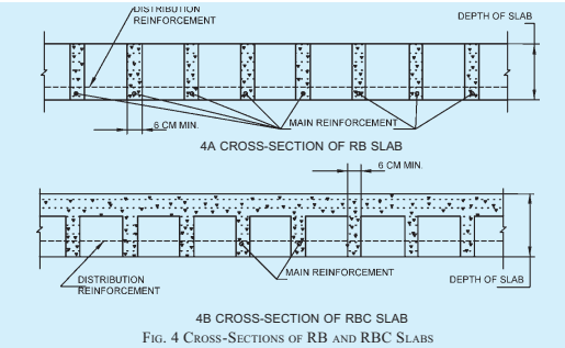
2.22 Reinforced Brick Slab (RB Slab) — Reinforced brick slab is particularly same as reinforced concrete slab in all its essential features except that brickwork is substituted partly for cement concrete. See Fig. 4A for details.
2.23 Reinforced Brick Concrete Slab (RBC Slab) — These are reinforced brick slab using concrete in the joints and on the top of bricks. See Fig. 4B for details.