18.5.1 Column Strength
When Pr/Pd is greater than 0.4, the requirements in 18.5.1.1 and 18.5.1.2 shall be met,
where
Pr = required compressive strength of the member as evaluated for load combination in Table 4, and
Pd = design strength in axial compression as obtained from 13.1.2.
18.5.1.1 The required axial compressive and axial tensile strength, shall be determined from the load combination in 18.2.3, without considering the simultaneous moments as obtained from the analysis.
18.5.1.2 The required axial strength determined in 18.5.1.1 need not exceed the maximum load transferred to the column considering 1.2 times the design strength of the connecting beam or brace element, or the resistance of the foundation to uplift.
18.5.2 Splices
18.5.2.1 A partial-joint penetration groove weld may be provided in axially loaded member splice, such that the design strength of the joints shall be at least equal to 200 percent of the required strength.
18.5.2.2 The minimum required strength for each flange splice shall be 1.2 times fyAf as shown in Fig. 20, where Af is the smaller of the area of each flange in the connected columns, and 1.2 times fyAw as minimum required strength in cases where web splices are provided.
18.5.2.3 The bolted column splice shall meet the requirements of 18.4 and 18.5.1.
18.6 Storey Drift
The storey drift limits shall conform to 5 of Part 6 'Structural Design, Section 1 Loads, Forces and Effects' of the Code. The deformation compatibility of members not designed to resist seismic lateral load shall also
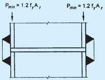
FIG. 20 PARTIAL PENETRATION GROOVE WELD IN COLUMN SPLICE
conform to 5 of Part 6 ‘Structural Design, Section 1 Loads, Forces and Effects’ of the Code.