Contact Pressure Distribution and Moments Below Flexible Foundation
E-1 Contact Pressure Distribution
E-1.1 The distribution of contact pressure is assumed to be linear with the maximum value attained under the columns and the minimum value at mid span.
E-1.2 The contact pressure for the full width of the strip under an interior column load located at a point i can be determined as (see Fig. 9 A):
where
average length of adjacent span, in m,
column load, in t at point , and
moment under an interior columns loaded at .
E-1.3 The minimum contact pressure for the full width of the strip at the middle of the adjacent spans can be determined as (see Fig. 9A and 9B):
where are as shown in Fig. 9A.
E-1.4 If E-2.3(a) governs the moment under the exterior columns, contact pressures under the exterior columns and at end of strip can be determined as (see Fig. 9C):
where are as shown in Fig. 9C.
E-1.5 If E-2.3(b) governs the moment under the exterior columns, the contact pressures are determined as (see Fig. 9C):
E-2 Bending Moment Diagram
E-2.1 The bending moment under an interior column located at (see Fig. 9A) can be determined as:
PART 6 STRUCTURAL DESIGN — SECTION 2 SOILS AND FOUNDATIONS
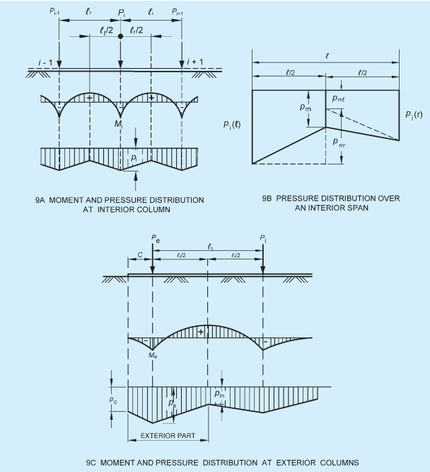
FIG. 9 MOMENT AND PRESSURE DISTRIBUTION AT COLUMNS
E-2.2 The bending moment at mid span is obtained as (see Fig. 9A):
where
moment of simply supported beam
average of negative moments at each end of the bay.
where are as shown in Fig. 9B.
E-2.3 The bending moment under exterior columns can be determined as the least of (see Fig. 9C):
a)
ANNEX F
[Clause 7.4.4.2(b)]
FLEXIBLE FOUNDATION — GENERAL CONDITION
F-1 Closed Form Solution of Elastic Plate Theory
F-1.1 For a flexible raft foundation with non-uniform column spacing and load intensity, solution of the differential equation governing the behaviour of plates on elastic foundation (Winkler Type) gives radial moment tangential moment and deflection at any point by the following expressions:
where
column load,
r = distance of the point under investigation from column load along radius, and
radius of effective stiffness
where
modulus of subgrade reaction for footing of width
flexural rigidity of the foundation,
raft thickness,
modulus of elasticity of the foundation material,
Possion's ratio of the foundation material, and
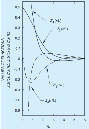
FIG. 10 FUNCTIONS FOR SHEAR, MOMENT AND DEFLECTION
F-1.2 The radial and tangential moments can be converted to rectangular co-ordinates:
where
angle with x-axis to the line joining origin to the point under consideration.
F-1.3 The shear, per unit width of raft can be determined by:
where
F-1.4 When the edge of the raft is located within the radius of influence, the following corrections are to be applied. Calculate moments and shears perpendicular to the edge of the raft within the radius of influence, assuming the raft to be infinitely large. Then apply
PART 6 STRUCTURAL DESIGN — SECTION 2 SOILS AND FOUNDATIONS
opposite and equal moments and shears on the edge of the mat. The method for beams on elastic foundation may be used.
F-1.5 Finally, all moments and shears calculated for each individual column and wall are superimposed to obtain the total moment and shear values.