Connections
E-1 General
The requirement for the design of splice and beam to column connection as well as recommendation for their design shall be as given below.
E-2 Beam Splices
E-2.1 For rolled section beam splices located away from the point of maximum moment, it may be assumed that the flange splice carries all the moment and the web splice carries the shear (see Fig. 30). However, in
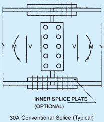
E-2.2 Flange joints should preferably not be located at points of maximum stress. Where splice plates are
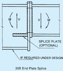
FIG. 30 BEAM SPLICES
the case of a deep girder, the total moment may be divided between the flange and the web in accordance with the stress distribution. The web connection should then be designed to resist its share of moment and shear. Even web splice is designed to carry only shear force, the moment about the centroid of the bolt group on either side of the splice should be designed for moment due to eccentricity.
E-2.3 When beam splice is located at the point of inflection of a continuous beam, the flange splicing requirement given above may be relaxed appropriately.
used, their area shall not be less than 5 percent in excess of the area of the flange element spliced; and their centre of gravity shall coincide, as nearly as possible with that of the element spliced. There shall be enough fasteners on each side of the splice to develop the load in the element spliced plus 5 percent but in no case should the strength developed be less than 50 percent of the effective strength of the material spliced. Wherever possible in welded construction, flange plates shall be joined by complete penetration butt welds. These butt welds shall develop the full strength of the plates. Whenever the flange width or thickness changes at the splice location, gradual transition shall be made in the width/thickness of the larger flange.
E-3 Column Splice
E-3.1 Where the ends of compression members are faced for bearing over the whole area, they shall be spliced to hold the connected parts aligned. The ends of compression members faced for bearing shall
invariably be machined to ensure perfect contact of surfaces in bearing (see Fig. 31).
E-3.2 Where such members are not faced for complete bearing the splices shall be designed to transmit all the forces to which the members is subjected at the splice location.
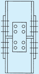
FIG. 31 COLUMN SPLICE (TYPICAL)
E-3.3 Wherever possible, splices shall be proportioned and arranged so that centroidal axis of the splice coincides as nearly as possible with the centroidal axes of the members joined, in order to avoid eccentricity; but where eccentricity is present in the joint, the resulting stress considering eccentricity shall be provided for.
E-3.4 If a column flange is subjected to significant tension or if the faces are not prepared for bearing, or if full continuity is required without slip, only HSFG bolts shall be used.
E-4 Beam-to-column Connections
E-4.1 Simple Connections
Simple connections are assumed to transfer only shear at some nominal eccentricity and typically used in frames up to about five stories in height, where strength rather
than stiffness govern the design. In such frames separate lateral load resisting system is to be provided in the form of bracings or shear walls. The connections shown in Figs. 32A, 32B, 32C and 32D can be assumed as simple connections in framed analysis and need to be checked only for the transfer of shear from beam to column.
E-4.2 Rigid Connections
In high-rise and slender structures, stiffness requirements may warrant the use of rigid connections. Rigid connections transfer significant moments to the columns and are assumed to undergo negligible deformations at the joint. These are necessary in sway frames for stability and also contribute in resisting lateral loads. The connections shown in Figs. 32E, 32F, and 32G can be assumed as rigid connection in frame analysis and need to be checked for both shear and
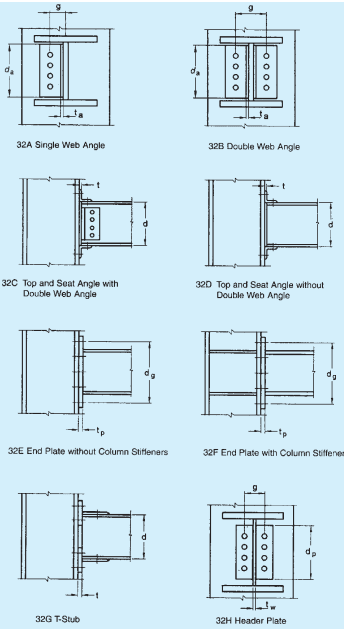
FIG. 32 SIZE PARAMETER FOR VARIOUS TYPES OF CONNECTION
PART 6 STRUCTURAL DESIGN — SECTION 6 STEEL
moment transfer from beam to the column. Fully welded connections can also be considered as rigid beam to column connections.
E-4.3 Semi-Rigid Connections
Semi-rigid connections fall between the two types mentioned above. The fact is that simple connections do have some degree of rotational rigidity as in the semi-rigid connections. Similarly rigid connections do experience some degree of joint deformation and this can be utilized to reduce the joint design moments.
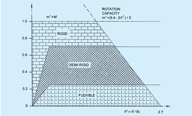
The moment-rotation relationship of the connections have to be determined based on experiments conducted for the specific design or based on the relationship derived from tests, presented in specialist literature. The simplest method of analysis will be to idealize the connection as an equivalent rotational spring with either a bilinear or nonlinear moment-rotation characteristics. The classification proposed by Bjorhovde combined with the Frye-Morris model can be used with convenience to model semi-rigid connections, as given in the next section.
E-4.3.1 Connection Classification
Connections are classified according to their ultimate strength or in terms of their initial elastic stiffness and Bjorhovde's classification. It is based on the non-dimensional moment parameter and the non-dimensional rotation parameter , where is the plastic rotation. The Bjorhovde's classification is based on a reference length of the beam equal to 5 times the depth of the beam. The limits used
E-4.3.2 Connection Models
Frye-Morris has derived the following polynomial model for the moment curvature relationship of semi-rigid connections:
E-5.1 Base Plates
Columns shall be provided with base plates capable of distributing the compressive forces in the compressed parts of the column over a bearing area such that the bearing pressure on the foundation does not exceed the design strength of the point. The design strength of the joint between the base plate and the foundation shall be determined taking account of the material properties and dimensions of both the grout and the concrete foundation.
E-5.2 Holding Down Bolts (Anchor Bolts)
E-5.2.1 Holding down bolts shall be provided, if
necessary to resist the effects of the design loads. They shall be designed to resist tension due to uplift forces and tension due to bending moments as appropriate.
E-5.2.2 When calculating the tension forces due to bending moments, the lever arm shall not be taken as more than the distance between the centroid of the bearing area on the compression side and the centroid of the bolt group on the tension side, taking the tolerances on the positions of the holding down bolts into account.
E-5.2.3 Holding down bolts shall either be anchored into the foundation by a hook or by a washer plate or by some other appropriate load distributing member embedded in the concrete.
E-5.2.4 If no special elements for resisting the shear force are provided, such as block or bar shear connectors, it shall be demonstrated that sufficient resistance to transfer the shear force between the column and the foundation is provided by one of the following:
a) Frictional resistance of the joint between the base plate and the foundation.
b) Shear resistance of the holding down bolts.
c) Shear resistance of the surrounding part of the foundation.
d) Shear and bearing resistance of the shear key plates welded to the base plate and embedded in the pedestal/foundation.