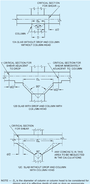
The term flat slab means a reinforced concrete slab with or without drops, supported generally without beams, by columns with or without flared column heads (see Fig. 12). A flat slab may be solid slab or may have recesses formed on the soffit so that the soffit comprises a series of ribs in two directions. The recesses may be formed by removable or permanent filler blocks.
30.1.1 For the purpose of this clause, the following definitions shall apply:
a) Column strip — Column strip means a design strip having a width of 0.25l2, but not greater than 0.25li on each side of the column centreline, where l1 is the span in the direction moments are being determined, measured centre-to-centre of supports and lz is the span transverse to l1, measured centre-to-centre of supports.
b) Middle strip — Middle strip means a design
strip bounded on each of its opposite sides by the column strip.
c) Panel — Panel means that part of a slab bounded on each of its four sides by the centreline of a column or centre-lines of adjacent spans.
30.2Proportioning
30.2.1 Thickness of Flat Slab
The thickness of the flat slab shall be generally controlled by considerations of span to effective depth ratios given in 22.2.
For slabs with drops conforming to 30.2.2, span to effective depth ratios given in 22.2 shall be applied directly; otherwise the span to effective depth ratios
NOTE — De is the diameter of column or column head to be considered for design and d is effective depth of slab or drop as appropriate.
FIG. 12 CRITICAL SECTIONS FOR SHEAR IN FLAT SLABS
obtained in accordance with provisions in 22.2 shall be multiplied by 0.9. For this purpose, the longer span shall be considered. The minimum thickness of slab shall be 125 mm.
30.2.2 Drop
The drops when provided shall be rectangular in plan, and have a length in each direction not less than one-third of the panel length in that direction. For exterior panels, the width of drops at right angles to the non-continuous edge and measured from the centre-line of the columns shall be equal to one-half the width of drop for interior panels.
30.2.3 Column Heads
Where column heads are provided, that portion of a column head which lies within the largest right circular cone or pyramid that has a vertex angle of 90∘ and can be included entirely within the outlines of the column and the column head, shall be considered for design purposes (see Fig. 12).
30.3Determination of Bending Moment
30.3.1 Methods of Analysis and Design
It shall be permissible to design the slab system by one of the following methods:
a) The direct design method as specified in 30.4, and
b) The equivalent frame method as specified in 30.5.
In each case the applicable limitations given in 30.4 and 30.5 shall be met.
30.3.2 Bending Moments in Panels with Marginal Beams or Walls
Where the slab is supported by a marginal beam with a depth greater than 1.5 times the thickness of the slab, or by a wall, then,
a) the total load to be carried by the beam or wall shall comprise those loads directly on the wall or beam plus a uniformly distributed load equal to one-quarter of the total load on the slab; and
b) the bending moments on the half-column strip adjacent to the beam or wall shall be one-quarter of the bending moments for the first interior column strip.
30.3.3 Transfer of Bending Moments to Columns
When unbalanced gravity load, wind, earthquake, or other lateral loads cause transfer of bending moment between slab and column, the flexural stresses shall be investigated using a fraction, α of the moment given by:
α=1+32a2a11
where
a1= overall dimension of the critical section for shear in the direction in which moment acts, and
a2= overall dimension of the critical section for shear transverse to the direction in which moment acts.
A slab width between lines that are one and one-half slab or drop panel thickness; 1.5 D, on each side of the column or capital may be considered effective, D being the size of the column.
Concentration of reinforcement over column head by closer spacing or additional reinforcement may be used to resist the moment on this section.
30.4Direct Design Method
30.4.1 Limitations
Slab system designed by the direct design method shall fulfill the following conditions:
a) There shall be minimum of three continuous spans in each direction,
b) The panels shall be rectangular, and the ratio of the longer span to the shorter span within a panel shall not be greater than 2.0,
c) It shall be permissible to offset columns to a maximum of 10 percent of the span in the direction of the offset notwithstanding the provision in (b),
d) The successive span lengths in each direction shall not differ by more than one-third of the longer span. The end spans may be shorter but not longer than the interior spans, and
e) The design live load shall not exceed three times the design dead load.
30.4.2 Total Design Moment for a Span
30.4.2.1 In the direct design method, the total design moment for a span shall be determined for a strip bounded laterally by the centre-line of the panel on each side of the centre-line of the supports.
30.4.2.2 The absolute sum of the positive and average negative bending moments in each direction shall be taken as :
Mo=8Wln
where
Mo=total moment;
PART 6 STRUCTURAL DESIGN — SECTION 5 CONCRETE: 5A PLAIN AND REINFORCED CONCRETE
W= design load on an area l2ln
ln = clear span extending from face to face of columns, capitals, brackets or walls, but not less than 0.65 l1 ;
l1= length of span in the direction of Mo ; and
l2= length of span transverse to l1
30.4.2.3 Circular supports shall be treated as square supports having the same area.
30.4.2.4 When the transverse span of the panels on either side of the centre-line of supports varies, l2 shall be taken as the average of the transverse spans.
30.4.2.5 When the span adjacent and parallel to an edge is being considered, the distance from the edge to the centre-line of the panel shall be substituted for l2 in 30.4.2.2.
30.4.3 Negative and Positive Design Moments
30.4.3.1 The negative design moment shall be located at the face of rectangular supports, circular supports being treated as square supports having the same area.
30.4.3.2 In an interior span, the total design moment M0 shall be distributed in the following proportions:
a) Negative design moment : 0.65
b) Positive design moment : 0.35
30.4.3.3 In an end span, the total design moment Mo shall be distributed in the following proportions:
a) Interior negative design moment:
0.75−1+αc10.10
b) Positive design moment:
0.63−1+αc10.28
c) Exterior negative design moment:
1+αc10.65
αc is the ratio of flexural stiffness of the exterior columns to the flexural stiffness of the slab at a joint taken in the direction moments are being determined and is given by:
αc=Ks∑Kc
where
Kc = sum of the flexural stiffness of the columns meeting at the joint; and
Ks = flexural stiffness of the slab, expressed as moment per unit rotation.
30.4.3.4 It shall be permissible to modify these design moments by up to 10 percent, so long as the total design moment, Mo for the panel in the direction considered is not less than that required by 30.4.2.2.
30.4.3.5 The negative moment section shall be designed to resist the larger of the two interior negative design moments determined for the spans framing into a common support unless an analysis is made to distribute the unbalanced moment in accordance with the stiffness of the adjoining parts.
30.4.4 Distribution of Bending Moments Across the Panel Width
Bending moments at critical cross-section shall be distributed to the column strips and middle strips as specified in 30.5.5 as applicable.
30.4.5 Moments in Columns
30.4.5.1 Columns built integrally with the slab system shall be designed to resist moments arising from loads on the slab system.
30.4.5.2 At an interior support, the supporting members above and below the slab shall be designed to resist the moment M given by the following equation, in direct proportion to their stiffnesses unless a general analysis is made:
54
M=0.08(1+αc1(wd+0.5wl)l2ln2−wd′l2′ln′2)
where
wd,w1= design dead and live loads respectively, per unit area;
l2=length of span transverse to the direction of M;
ln = length of the clear span in the direction of M, measured face to face of supports;
αc=∑Ks∑Kc where Kc and Ks are as defined in 30.4.3.3; and
wd′,l2′ and ln′ refer to the shorter span.
30.4.6 Effects of Pattern Loading
In the direct design method, when the ratio of live load to dead load exceeds 0.5,
a) the sum of the flexural stiffness of the columns above and below the slab, ∑Kc , shall be such that αc is not less than the appropriate minimum value αcmin specified in Table 17; or
b) if the sum of the flexural stiffnesses of the columns, ∑Kc , does not satisfy (a), the positive design moments for the panel shall be multiplied by the coefficient βs given by the following equation :
βs=1+[4+wlwd2−wlwd](1−αcminαc)
αc is the ratio of flexural stiffness of the columns above and below the slab to the flexural stiffness of the slabs at a joint taken in the direction moments are being determined and is given by:
αc=∑Ks∑Kc
where Kc and Ks are flexural stiffnesses of column and slab respectively.
Table 17Minimum Permissible Values of \alpha_{\mathrm{c}} (Clause 30.4.6)
Sl No.
Imposed Load/Dead Load
Ratio l2l1
Value of αcmin
(1)
(2)
(3)
(4)
i)
0.5
0.5 to 2.0
0
ii)
1.0
0.5
0.6
iii)
1.0
0.8
0.7
iv)
1.0
1.0
0.7
v)
1.0
1.25
0.8
vi)
1.0
2.0
1.2
vii)
2.0
0.5
1.3
viii)
2.0
0.8
1.5
ix)
2.0
1.0
1.6
x)
2.0
1.25
1.9
xi)
2.0
2.0
4.9
xii)
3.0
0.5
1.8
xiii)
3.0
0.8
2.0
xiv)
3.0
1.0
2.3
xv)
3.0
1.25
2.8
xvi)
3.0
2.0
13.0
30.5Equivalent Frame Method
30.5.1 Assumptions
The bending moments and shear forces may be determined by an analysis of the structure as a continuous frame and the following assumptions may be made:
a) The structure shall be considered to be made up of equivalent frames on column lines taken longitudinally and transversely through the building. Each frame consists of a row of equivalent columns or supports, bounded laterally by the centre-line of the panel on each side of the centre-line of the columns or supports. Frames adjacent and parallel to an edge shall be bounded by the edge and the centre-line of the adjacent panel.
b)
Each such frame may be analysed in its entirety, or, for vertical loading, each floor thereof and the roof may be analysed separately with its columns being assumed fixed at their remote ends. Where slabs are thus analysed separately, it may be assumed in determining the bending moment at a given support that the slab is fixed at any support two panels distant therefrom provided the slab continuous beyond the point.
c) For the purpose of determining relative stiffness of members, the moment of inertia of any slab or column may be assumed to be that of the gross cross-section of the concrete alone.
d) Variations of moment of inertia along the axis of the slab on account of provision of drops shall be taken into account. In the case of recessed or coffered slab which is made solid in the region of the columns, the stiffening effect may be ignored provided the solid part of the slab does not extend more than 0.15lef , into the span measured from the centre-line of the columns. The stiffening effect of flared column heads may be ignored.
30.5.2 Loading Pattern
30.5.2.1 When the loading pattern is known, the structure shall be analysed for the load concerned.
30.5.2.2 When the live load is variable but does not exceed three-quarters of the dead load, or the nature of the live load is such that all panels will be loaded simultaneously, the maximum moments may be assumed to occur at all sections when full design live load is on the entire slab system.
30.5.2.3 For other conditions of live load/dead load ratio and when all panels are not loaded simultaneously,
a) maximum positive moment near midspan of a panel may be assumed to occur when three-quarters of the full design live load is on the panel and on alternate panels; and
b) maximum negative moment in the slab at a support may be assumed to occur when three-quarters of the full design live load is on the adjacent panels only.
PART 6 STRUCTURAL DESIGN — SECTION 5 CONCRETE: 5A PLAIN AND REINFORCED CONCRETE
30.5.2.4 In no case shall design moments be taken to be less than those occurring with full design live load on all panels.
30.5.3 Negative Design Moment
30.5.3.1 At interior supports, the critical section for negative moment, in both the column strip and middle strip, shall be taken at the face of rectilinear supports, but in no case at a distance greater than 0.175l1 from the centre of the column where l1 is the length of the span in the direction moments are being determined, measured centre-to-centre of supports.
30.5.3.2 At exterior supports provided with brackets or capitals, the critical section for negative moment in the direction perpendicular to the edge shall be taken at a distance from the face of the supporting element not greater than one-half the projection of the bracket or capital beyond the face of the supporting element.
30.5.3.3 Circular or regular polygon shaped supports shall be treated as square supports having the same area.
30.5.4 Modification of Maximum Moment
Moments determined by means of the equivalent frame method, for slabs which fulfil the limitations of 30.4 may be reduced in such proportion that the numerical sum of the positive and average negative moments is not less than the value of total design moment Mo specified in 30.4.2.2.
30.5.5 Distribution of Bending Moment Across the Panel Width
30.5.5.1 Column strip : Negative moment at an interior support
At an interior support, the column strip shall be designed to resist 75 percent of the total negative moment in the panel at that support.
30.5.5.2 Column strip : Negative moment at a exterior support
a) At an exterior support, the column strip shall be designed to resist the total negative moment in the panel at that support.
b) Where the exterior support consists of a column or a wall extending for a distance equal to or greater than three-quarters of the value of l2∘ the length of span transverse to the direction moments are being determined, the exterior negative moment shall be considered to be uniformly distributed across the length l2.
30.5.5.3 Column strip : Positive moment for each span
For each span, the column strip shall be designed to resist 60 percent of the total positive moment in the panel.
30.5.5.4 Moments in the middle strip
The middle strip shall be designed on the following bases:
a) That portion of the design moment not resisted by the column strip shall be assigned to the adjacent middle strips.
b) Each middle strip shall be proportioned to resist the sum of the moments assigned to its two half middle strips.
c) The middle strip adjacent and parallel to an edge supported by a wall shall be proportioned to resist twice the moment assigned to half the middle strip corresponding to the first row of interior columns.
30.6Shear in Flat Slab
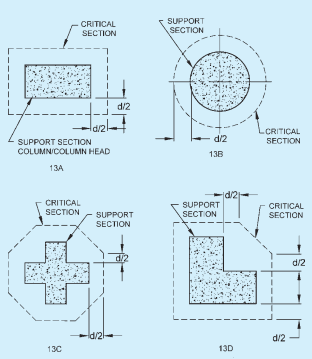
30.6.1 The critical section for shear shall be at a distance d/2 from the periphery of the column/capital/ drop panel, perpendicular to the plane of the slab where d is the effective depth of the section (see Fig. 12). The shape in plan is geometrically similar to the support immediately below the slab (see Fig. 13A and Fig.13B).
NOTE — For column sections with re-entrant angles, the critical section shall be taken as indicated in Fig. 13C and Fig. 13D.
NOTE — d is the effective depth of the flat slab/drop.
FIG. 13 CRITICAL SECTIONS IN PLAN FOR SHEAR IN FLAT SLABS
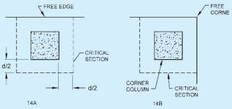
30.6.1.1 In the case of columns near the free edge of a slab, the critical section shall be taken as shown in Fig. 14.
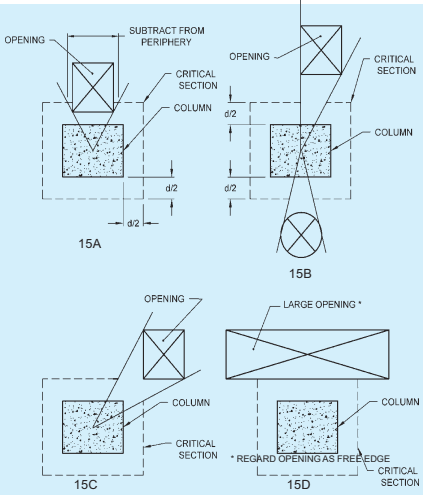
30.6.1.2 When openings in flat slabs are located at a distance less than ten times the thickness of the slab from a concentrated reaction or when the openings are located within the column strips, the critical sections specified in 30.6.1 shall be modified so that the part of the periphery of the critical section which is enclosed by radial projections of the openings to the centroid of the reaction area shall be considered ineffective (see Fig. 15), and openings shall not encroach upon column head.
30.6.2 Calculation of Shear Stress
The shear stress τv shall be the sum of the values calculated according to 30.6.2.1 and 30.6.2.2.
30.6.2.1 The nominal shear stress in flat slabs shall be taken as Vb0d where V is the shear force due to design load, bo is the periphery of the critical section and d is the effective depth.
FIG. 14 EFFECT OF FREE EDGES ON CRITICAL SECTION FOR SHEAR
FIG. 15 EFFECT OF OPENINGS ON CRITICAL SECTION FOR SHEAR
PART 6 STRUCTURAL DESIGN — SECTION 5 CONCRETE: 5A PLAIN AND REINFORCED CONCRETE
30.6.2.2 When unbalanced gravity load, wind, earthquake or other forces cause transfer of bending moment between slab and column, a fraction (1−α) of the moment shall be considered transferred by eccentricity of the shear about the centroid of the critical section. Shear stresses shall be taken as varying linearly about the centroid of the critical section. The value of aˊ shall be obtained from the equation given in 30.3.3.
30.6.3 Permissible Shear Stress
30.6.3.1 When shear reinforcement is not provided, the calculated shear stress at the critical section shall not exceed ksτc ,
where
ks=(0.5+βc) but not greater than 1, βc being the ratio of short side to long side of the column/capital; and
τc=0.25fck in limit state method of design, and 0.16fck in working stress method of design.
30.6.3.2 When the shear stress at the critical section exceeds the value given in 30.6.3.1, but less than 1.5τc shear reinforcement shall be provided. If the shear stress exceeds 1.5τc , the flat slab shall be redesigned. Shear stresses shall be investigated at successive sections more distant from the support and shear reinforcement shall be provided up to a section where the shear stress does not exceed 0.5τc . While designing the shear reinforcement, the shear stress carried by the concrete shall be assumed to be 0.5τc and reinforcement shall carry the remaining shear.
30.7Slab Reinforcement
30.7.1 Spacing
The spacing of bars in a flat slab, shall not exceed 2 times the slab thickness, except where a slab is of cellular or ribbed construction.
30.7.2 Area of Reinforcement
When drop panels are used, the thickness of drop panel for determination of area of reinforcement shall be the lesser of the following:
a) Thickness of drop, and
b) Thickness of slab plus one quarter the distance between edge of drop and edge of capital.
30.7.3 Minimum Length of Reinforcement
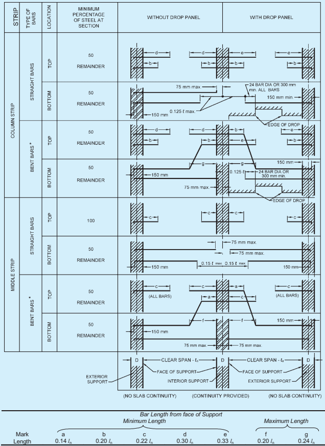
a) Reinforcement in flat slabs shall have the minimum lengths specified in Fig. 16. Larger lengths of reinforcement shall be provided when required by analysis.
b) Where adjacent spans are unequal, the extension of negative reinforcement beyond each face of the common column shall be based on the longer span.
c) The length of reinforcement for slabs in frames not braced against sideways and for slabs resisting lateral loads shall be determined by analysis but shall not be less than those prescribed in Fig. 16.
30.7.4 Anchoring Reinforcement
a) All slab reinforcement perpendicular to a discontinuous edge shall have an anchorage (straight, bent or otherwise anchored) past the internal face of the spandrel beam, wall or column, of an amount :
For positive reinforcement – Not less than 150 mm except that with fabric reinforcement having a fully welded transverse wire directly over the support, it shall be permissible to reduce this length to one-half of the width of the support or 50 mm, whichever is greater; and
For negative reinforcement – Such that the design stress is developed at the internal face, in accordance with Section 5A (C).
b) Where the slab is not supported by a spandrel beam or wall, or where the slab cantilevers beyond the support, the anchorage shall be obtained within the slab.
30.8Openings in Flat Slabs
Openings of any size may be provided in the flat slab, if it is shown by analysis that the requirements of strength and serviceability are met. However, for openings conforming to the following, no special analysis is required.
a) Openings of any size may be placed within the middle half of the span in each direction, provided the total amount of reinforcement required for the panel without the opening is maintained.
b) In the area common to two column strips, not more than one-eighth of the width of strip in either span shall be interrupted by the openings. The equivalent of reinforcement interrupted shall be added on all sides of the openings.
c) In the area common to one column strip and one middle strip, not more than one-quarter of the reinforcement in either strip shall be interrupted by the openings. The equivalent
Bar Length from face of SupportMinimum Length
Maximum Length
Mark Length
a 0.14ln
b 0.20ln
c 0.22ln
d 0.30ln
e 0.33ln
f 0.20ln
g 0.24ln
* Bent bars at exterior supports may be used, if a general analysis is made.
NOTE — D is the diameter of the column and the dimension of the rectangular column in the direction under consideration.
FIG. 16 MINIMUM BEND JOINT LOCATION AND EXTENSION FOR REINFORCEMENT IN FLAT SLABS
PART 6 STRUCTURAL DESIGN — SECTION 5 CONCRETE: 5A PLAIN AND REINFORCED CONCRETE
of reinforcement interrupted shall be added on all sides of the openings.
d) The shear requirements of 30.6 shall be satisfied.