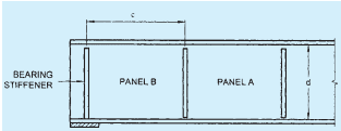
14.7.1 General
14.7.1.1 When the web of a member acting alone (that is, without stiffeners) proves inadequate, stiffeners for meeting the following requirements should be provided:
a) Intermediate transverse web stiffener — To improve the buckling strength of a slender web due to shear (see 14.7.2).
b) Load carrying stiffener — To prevent local buckling of the web due to concentrated loading (see 14.7.3 and 14.7.5).
c) Bearing stiffener — To prevent local crushing of the web due to concentrated loading (see 14.7.4 and 14.7.6).
d) Torsion stiffener — To provide torsional restraint to beams and girders at supports (see 14.7.9).
e) Diagonal stiffener — To provide local reinforcement to a web under shear and bearing (see 14.7.7).
f) Tension stiffener — To transmit tensile forces applied to a web through a flange (see 14.7.8).
The same stiffeners may perform more than one function and their design should comply with the requirements of all the functions for which designed.
14.7.1.2 Outstand of web stiffeners
Unless the outer edge is continuously stiffened, the outstand from the face of the web should not exceed 20tqε .
When the outstand of web stiffener is between 14tqε and 20tqε , then the stiffener design should be on the basis of a core section with an outstand of only 14tqε , where tq is the thickness of the stiffener.
14.7.1.3 Stiff bearing length
The stiff bearing length of any element, b1 , is that length which cannot deform appreciably in bending. To determine b1 , the dispersion of load through a steel bearing element should be taken as 45∘ through solid material, such as bearing plates, flange plates, etc (see Fig.15).
14.7.1.4 Eccentricity
Where a load or reaction is applied eccentric to the centerline of the web or where the centroid of the stiffener does not lie on the centerline of the web, the resulting eccentricity of loading should be accounted for in the design of the stiffener.
14.7.1.5 Buckling resistance of stiffeners
The buckling resistance Fqd should be based on the design compressive stress fcd (see 13.1.2.1) of a strut (curve c), the radius of gyration being taken about the axis parallel to the web. The effective section is the full area or core area of the stiffener (see 14.7.1.2) together with an effective length of web on each side of the centerline of the stiffeners, limited to 20 times the web thickness. The design strength used should be the minimum value obtained for buckling about the web or the stiffener.
The effective length for intermediate transverse stiffeners used in calculating the buckling resistance,
Fqd, should be taken as 0.7 times the length, L of the stiffener.
The effective length for load carrying web stiffeners used in calculating the buckling resistance, Fxd , assumes that the flange through which the load or reaction is applied is effectively restrained against lateral movement relative to the other flange, the effective length should be taken as:
a) KL=0.7L, when flange is restrained against rotation in the plane of the stiffener (by other structural elements), and
b) KL=L, when flange is not so restrained
where
L= length of the stiffener.
If the load or reaction is applied to the flange by a compression member, then unless effective lateral restraint is provided at that point, the stiffener should be designed as part of the compression member applying the load, and the connection between the column and beam flange shall be checked for the effects of the strut action.
14.7.2 Design of Intermediate Transverse Web Stiffeners
14.7.2.1 General
Intermediate transverse stiffeners may be provided on one or both sides of the web.
14.7.2.2 Spacing
Spacing of intermediate stiffeners, where provided, shall comply with 14.6.1 depending on the thickness of the web.
14.7.2.3 Outstand of stiffeners
The outstand of the stiffeners should comply with 14.7.1.2.
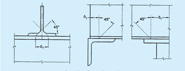
FIG. 15 STIFF BEARING LENGTH, b1
PART 6 STRUCTURAL DESIGN — SECTION 6 STEEL
14.7.2.4 Minimum stiffeners
Transverse web stiffeners not subject to external loads or moments should have a second moment of area, Is about the centreline of the web, if stiffeners are on both sides of the web and about the face of the web, if single stiffener on only one side of the web is used such that:
where
d= depth of the web;
tw = minimum required web thickness for spacing using tension field action, as given in 14.4.2.1; and
c= actual stiffener spacing.
Stiffeners not subjected to external loads or moments should be checked for a stiffener force:
where
Fqd=design resistance of the intermediate stiffeners;
V= factored shear force adjacent to the stiffener; and
Vcr = shear buckling resistance of the web panel designed without using tension field action as given in 14.4.2.2 a).
Stiffeners subject to external loads and moments should meet the conditions for load carrying web stiffeners in 14.7.3. In addition they should satisfy the following interaction expression:
where
Fq= stiffener force given above;
Fqd= design resistance of an intermediate web stiffener corresponding to buckling about an axis parallel to the web (see 14.7.1.5);
Fxd= design resistance of a load carrying stiffener corresponding to buckling about axis parallel to the web (see 14.7.1.5);
Mq= moment on the stiffener due to eccentrically applied load and transverse load, if any; and
Myq= yield moment capacity of the stiffener based on its elastic modulus about its centroidal axis parallel to the web.
If Fq<Fx, then (Fq−Fx) should be taken as zero;
Intermediate transverse stiffeners not subject to external loading should be connected to the web so as to withstand a shear between each component of the stiffener and the web (in kN/mm) of not less than:
where
tw=web thickness, in mm; and
bs= outstand width of the stiffener, in mm.
For stiffeners subject to external loading, the shear between the web and the stiffener due to such loading has to be added to the above value.
Stiffeners not subject to external loads or moments may terminate clear of the tension flange and in such a situation the distance cut short from the line of the weld should not be more than 4tw .
14.7.3 Load Carrying Stiffeners
14.7.3.1 Web check
Load carrying web stiffeners should be provided where compressive forces applied through a flange by loads or reactions exceed the buckling strength, Fcdw , of the unstiffened web, calculated using the following:
The effective length of the web for evaluating the slenderness ratio is calculated as in 14.7.1.5. The area of cross-section is taken as (b1+n1)tw.
where
b1 = width of stiff bearing on the flange (see 14.7.1.3), and
n1 = dispersion of the load through the web at 45∘ , to the level of half the depth of the cross-section.
The buckling strength of this web about axis parallel to the web is calculated as given in 13.1.2.1, using curve 'c'.
14.7.4 Bearing Stiffeners
Bearing stiffeners should be provided for webs where forces applied through a flange by loads or reactions exceeding the local capacity of the web at its connection to the flange, Fw , given by:
where
n2 = length obtained by dispersion through the flange to the web junction at a slope of 1:2.5 to the plane of the flange,
tw = thickness of the web, and
fyw= yield stress of the web.
14.7.5 Design of Load Carrying Stiffeners
14.7.5.1 Buckling check
The external load or reaction, Fx on a stiffener should not exceed the buckling resistance, Fxd of the stiffener as given in 14.7.1.5.
Where the stiffener also acts as an intermediate stiffener it should be checked for the effect of combined loads in accordance with 14.7.2.5.
14.7.5.2 Bearing check
Load carrying web stiffeners should also be of sufficient size that the bearing strength of the stiffener, Fpsd, given below is not less than the load transferred, Fx
where
Fx= external load or reaction,
Aq = area of the stiffener in contact with the flange, and
fyq= yield stress of the stiffener.
14.7.6 Design of Bearing Stiffeners
Bearing stiffeners should be designed for the applied load or reaction less the local capacity of the web as given in 14.7.4. Where the web and the stiffener material are of different strengths the lesser value should be assumed to calculate the capacity of the web and the stiffener. Bearing stiffeners should project nearly as much as the overhang of the flange through which load is transferred.
14.7.7 Design of Diagonal Stiffeners
Diagonal stiffeners should be designed to carry the portion of the applied shear and bearing that exceeds the capacity of the web.
Where the web and the stiffener are of different strengths, the value for design should be taken as given in 14.7.6.
14.7.8 Design of Tension Stiffeners
Tension stiffeners should be designed to carry the portion of the applied load or reaction less the capacity of the web as given in 14.7.4 for bearing stiffeners.
Where the web and the stiffener are of different strengths, the value for design should be taken as given in 14.7.6.
14.7.9 Torsional Stiffeners
Where bearing stiffeners are required to provide torsional restraint at the supports of the beam, they should meet the following criteria:
a) Conditions of 14.7.4, and
b) Second moment of area of the stiffener section about the centerline of the web, Is should be such that:
where
D= Overall depth of beam at support,
Tcf= Maximum thickness of compression flange in the span under consideration,
KL= Laterally unsupported effective length of the compression flange of the beam, and
ry = Radius of gyration of the beam about the minor axis.
14.7.10 Connection to Web of Load Carrying and Bearing Stiffeners
Stiffeners, which resist loads or reactions applied through a flange, should be connected to the web by sufficient welds or fasteners to transmit a design force equal to the lesser of,
a) tension capacity of the stiffener; and
b) sum of the forces applied at the two ends of the stiffener when they act in the same direction or the larger of the forces when they act in opposite directions.
Stiffeners, which do not extend right across the web, should be of such length that the shear stress in the web due to the design force transmitted by the stiffener does not exceed the shear strength of the web. In addition, the capacity of the web beyond the end of the stiffener should be sufficient to resist the applied force.
14.7.11 Connection to Flanges
14.7.11.1 In tension
Stiffeners required to resist tension should be connected to the flange transmitting the load by continuous welds or non-slip fasteners.
14.7.11.2 In compression
Stiffeners required to resist compression should either be fitted against the loaded flange or connected by continuous welds or non-slip fasteners.
The stiffener should be fitted against or connected to both flanges when,
PART 6 STRUCTURAL DESIGN — SECTION 6 STEEL
a) a load is applied directly over a support; or
b) it forms the end stiffener of a stiffened web; or
c) it acts as a torsion stiffener.
14.7.12 Hollow Sections
Where concentrated loads are applied to hollow sections consideration should be given to local stresses and deformations and the section reinforced as necessary.
14.7.13 Horizontal Stiffeners
Where horizontal stiffeners are used in addition to vertical stiffeners, they shall be as follows:
a) One horizontal stiffener shall be placed on the web at a distance from the compression flange equal to 1/5 of the distance from the compression flange angle, plate or tongue plate to the neutral axis when the thickness of the web is less than the limits specified in 14.6.1. The stiffener shall be designed so that Is is not less than 4ctw3 where Is and tw are as defined in 14.7.2.4 and c is the actual distance between the vertical stiffeners;
b) A second horizontal stiffener (single or double) shall be placed at the neutral axis of the girder when the thickness of the web is less than the limit specified in 14.6.1. This stiffener shall be designed so that Is is not less than d2tw3 where Is and tw are as defined in 14.7.2.4 and d2 is twice the clear distance from the compression flange angles, plates or tongue plates to the neutral axis;
c) Horizontal web stiffeners shall extend between vertical stiffeners, but need not be continuous over them; and
d) Horizontal stiffeners may be in pairs arranged on each side of the web, or single located on one side of the web.