7.6.1.1 General
During an impact, the kinetic impact energy has to be absorbed by the vehicle hitting the structure and by the structure itself. In an accurate analysis, the probability of occurrence of an impact with a certain energy object hitting the structure and the structure itself at the actual place shall be considered. Impact energies for dropped object should be based on the actual loading capacity and lifting height.
Common sources of impact are:
a) Vehicles;
b) Dropped objects from cranes, fork lifts, etc;
c) Cranes out of control, crane failures; and
d) Flying fragments.
The codal requirements regarding impact from vehicles and cranes are given in 7.6.1.2 and 7.6.1.3.
7.6.1.2 The requirements for loads as a result of collision between vehicle and structural or non-structural elements shall be as per 7.6.1.2.1 and 7.6.1.2.2.
7.6.1.2.1 Collisions between vehicles and structural elements
In road traffic, the requirement that a structure shall be able to resist collision may be assumed to be fulfilled, if it is demonstrated that the structural element is able to stop a fictitious vehicle, as described below. It is assumed that the vehicle strikes the structural element at a height of 1.2 m in any possible direction and at a speed of 10 m/s (36 km/h).
The fictitious vehicle shall be considered to consist of two masses m1 and m2 which during compression of the vehicle, produce an impact force increasing uniformly from zero, corresponding to the rigidities C1 and C2. It is assumed that the mass m1 is broken completely before the breaking of mass m2 begins.
The following numerical values should be used:
m1=400kg,C1=10000kN/m, the vehicle is compressed.
m2=12 000 kg,C2=300 kN/m, the vehicle is compressed.
PART 6 STRUCTURAL DESIGN — SECTION 1 LOADS, FORCES AND EFFECTS
NOTE — The described fictitious collision corresponds in the case of a non-elastic structural element to a maximum static force of 630 kN for the mass m1 and 600 kN for the mass m2 irrespective of the elasticity, it will therefore be on the safe side to assume the static force to be 630 kN.
In addition, breaking of the mass m1 will result in an impact wave, the effect of which will depend, to a great extent, on the kind of structural element concerned. Consequently, it will not always be sufficient to design for the static force.
7.6.1.2.1.1 For structural elements in stilts and car parking levels
For structural elements in stilts and car parking levels, where driveways and car parking are provided in the buildings which have limited vehicle speeds, the design shall take care of the following considerations:
a) Speed of the vehicle to be 20 km/h maximum (since within a building and inside the car parks, speed of the vehicle may not generally be more than 20 km/h).
b) Impact to be considered at a height of 450 mm to 600 mm.
Structural elements such as columns, RC walls or vertical load resisting elements shall be designed for loads due to the above unless protected by separate resisting system.
7.6.1.2.2 Collision between vehicles and non-structural elements
Non-structural elements, such as vehicle barriers for car parks shall be designed to resist the impact and the momentum as outlined below:
a) The horizontal force F (in kN), normal to and uniformly distributed over any length of 1.5 m of a barrier for a car park, required to withstand the impact of a vehicle shall be as given below:
where
m= gross mass of the vehicle, in kg;
v = velocity of the vehicle normal to the barrier, in m/s;
δc= deformation of the vehicle, in mm;
δb= deflection of the barrier, in mm.
b) Where the car park has been designed on the basis that the gross mass of the vehicles using it will not exceed 2 500 kg, the following values shall be used to determine the force F:
For a rigid barrier, for which δb may be taken as zero, the force, F, appropriate to vehicles up to 2 500 kg gross mass, shall be taken as 150 kN.
c) Where the car park has been designed for vehicles whose gross mass exceeds 2 500 kg, the following values shall be used to determine the force F:
m = actual mass of the vehicle for which the car park is designed, in kg;
v=4.5m/s; and
d) The force determined as in (b) or (c) may be considered to act at bumper height. In the case of car parks intended for motor cars whose gross mass does not exceed 2 500 kg, this height may be taken as 375 mm above the floor level.
e) Barriers to access ramps of car parks have to withstand one-half of the force determined in (b) or (c) acting at a height of 610 mm above the ramp.
Opposite to the ends of straight ramps intended for downward travel, which exceed 20 m in length, the barrier shall be designed to withstand twice the force determined in (b) or (c) acting at a height of 610 mm above the ramp.
NOTE — The mass of 1 500 kg is taken as being more representative of the vehicle population than the extreme value of 2 500 kg.
7.6.1.3 Safety railings
With regard to safety, railings put up to protect structures against collision due to road traffic, it should be shown that the railings are able to resist the impact as described in 7.6.1.2.
NOTE — When a vehicle collides with safety railings, the kinetic energy of the vehicle will be absorbed partly by the deformation of the railings and partly by the deformation of the vehicle. The part of the kinetic energy which the railings should be able to absorb without breaking down may be determined on the basis of the assumed rigidity of the vehicle during compression.
7.6.1.4 Crane impact load on buffer stop
The basic horizontal load Py (tonne), acting along the crane track produced by impact of the crane on the buffer stop, is calculated by the following formula:
where
V= speed at which the crane is traveling at the moment of impact (assumed equal to half the nominal value) (m/s)
F= maximum shortening of the buffer, assumed
equal to 0.1 m for light duty, medium-duty and heavy-duty cranes with flexible load suspension and loading capacity not exceeding 50 t, and 0.2 m in every other cranes.
M= reduced crane mass, (t.s2/m) ; and is obtained by the formula:
where
Ph= crane bridge weight (t);
Q= crane loading capacity (t);
k = coefficient, assumed equal to zero for cranes with flexible load suspension and to one for cranes with rigid suspension;
Lk= crane span (m); and
l= nearness of crab (m).
7.6.2 Explosions
7.6.2.1 General
Explosions may cause impulsive loading on a structure. The following types of explosions are particularly relevant:
a) Internal gas explosions which may be caused by leakage of gas piping (including piping outside the room), evaporation from volatile liquids or unintentional evaporation from surface material (for example, fire);
b) Internal dust explosions;
c) Boiler failure;
d) External gas cloud explosions; and
e) External explosions of high explosives (TNT, dynamite).
The codal requirement regarding internal gas explosions is given in 7.6.2.2.
7.6.2.2 Explosion effect in closed rooms
Gas explosion may be caused, for example by leaks in gas pipes (inclusive of pipes outside for room), evaporation from volatile liquids or unintentional evaporation of gas from wall sheathings (for example, caused by fire).
1 The effect of explosions depends on the exploding medium, the concentration of the explosion, the shape of the room, possibilities of ventilation of the explosion, and the ductility and dynamic properties of the structure. In rooms with little possibility for relief of the pressure from the explosion, very large pressures may occur.
Internal over pressure from an internal gas explosion in rooms of sizes comparable to residential rooms and with ventilation
areas consisting of window glass breaking at a pressure of 4kN/m2 (3-4 mm machine made glass) may be calculated from the following method:
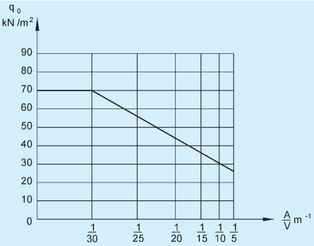
a) The over pressure is assumed to depend on a factor A/V, where A is the total windows area, in m2, and V is the volume, in m3, of the room considered;
b) The internal pressure is assumed to act simultaneously upon all walls and floors in one closed room; and
c) The action qo may be taken as static action.
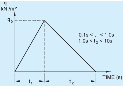
If account is taken of the time curve of the action, the schematic correspondence between pressure and time is assumed (see Fig. 19), where t1 is the time from the start of combustion until maximum pressure is reached and t2 is the time from maximum pressure to the end of combustion. For t1 and t2, the most unfavourable values should be chosen in relation to the dynamic properties of the structures. However, the values should be chosen within the intervals as given in Fig. 20.
2 Figure 19 is based on tests with gas explosions in room corresponding to ordinary residential flats and should, therefore, not be applied to considerably different conditions. The figure corresponds to an explosion caused by town gas and it might, therefore, be somewhat on the safe side in rooms where there is only the possibility of gases with a lower rate of combustion.
The pressure may be applied solely in one room or in more rooms at the same time. In the latter case, all rooms are incorporated in the volume V. Only windows or other similarly weak and light weight structural elements may be taken to be ventilation areas even though certain limited structural parts break at pressures less than qo.
Figure 19 is given purely as guide and probability of occurrence of an explosion should be checked in each case using appropriate values.