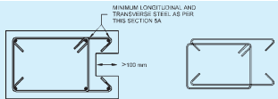
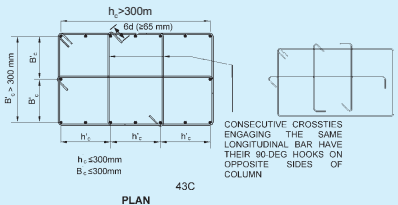
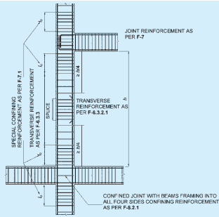
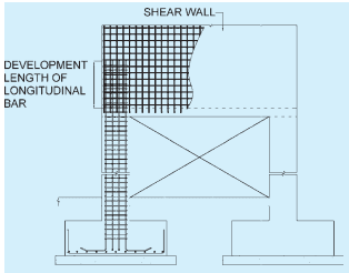
For the purpose of this annex, the following letter symbols shall have the meaning indicated against each; where other symbols are used, they are explained at the appropriate place. All dimensions in millimetre, loads in Newton and stresses in MPa, unless otherwise specified.
Ae = Effective cross-sectional area of a joint
Aej = Effective shear area of a joint
Ag = Gross cross-sectional area of column, wall
Ah = Horizontal reinforcement area within spacing sv
Ak = Area of concrete core of column
Asd = Reinforcement along each diagonal of coupling beam
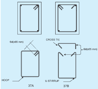
Ash = Area of cross-section of bar forming spiral or link
Ast = Area of uniformly distributed vertical reinforcement
Av = Vertical reinforcement at a joint
bb = Width of beam
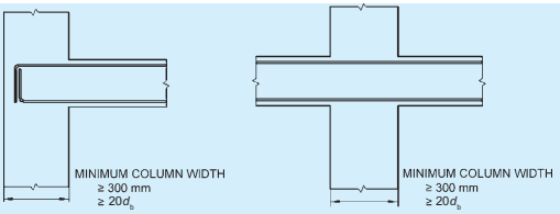
bc = Width of column
bj = Effective width of a joint
D = Overall depth of beam
Dk = Diameter of column core measured to the outside of spiral or link
d = Effective depth of member
db = Diameter of longitudinal bar
dw = Effective depth of wall section
Es= Elastic modulus of steel
fck=Characteristic compressive strength of concrete cube, in MPa
fy= Yield stress of steel reinforcing bars, or 0.2 percent proof strength of reinforcing steel, in MPa
h = Longer dimension of rectangular confining link measured to its outer face
hj= Effective depth of a joint
hw= Overall height of RC structural wall
lo= Length of member over which special confining reinforcement is to be provided
Lw= Horizontal length of wall/longer cross-section dimension of wall
Ls= Clear span of couplings beam
Mu= Design moment of resistance of entire RC beam, column or wall section
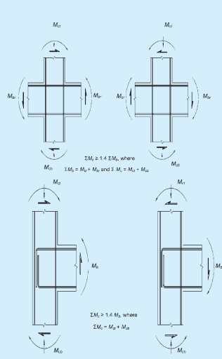
Mc1=Design moment of resistance of column section
Mc2=Design moment of resistance of column section
Mg1=Design moment of resistance of beam section
Mg2=Design moment of resistance of beam section
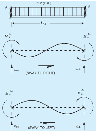
MuAh=Hogging design moment of resistance of beam at end A
MuAs=Sagging design moment of resistance of beam at end A
MuBh = Hogging design moment of resistance of beam at end B
MuBs=Sagging design moment of resistance of beam at end B
MuBL=Design moment of resistance of beam framing into column from the left
MuBR = Design moment of resistance of beam framing into column from the right
Muw= Design moment of resistance of web of RC structural wall alone
Pu= Factored axial load
sv= Spacing of links along the longitudinal direction of beam or column
tw= Thickness of web of RC structural wall
Vu,aD+L= Factored shear force demand at end A of beam due to dead and live loads
Vu,bD+L= Factored shear force demand at end B of beam due to dead and live loads
Vj= Design shear resistance of a joint
Vu= Factored shear force
Vus= Design shear resistance offered at a section by steel links
xuxu∗= Depth of neutral axis from extreme compression fibre
α= Inclination of diagonal reinforcement in coupling beam
ρ= Area of longitudinal reinforcement as a fraction of gross area of cross-section in a RC beam, column or structural wall
ρc= Area of longitudinal reinforcement on the compression face of a beam as a fraction of gross area of cross-section
(ρh)min= Minimum area of horizontal reinforcement of a structural wall as a fraction of gross area of cross-section
(ρv,be)min= Minimum area of vertical reinforcement in each boundary element of a structural wall as a fraction of gross area of cross-section of each boundary element
(ρv,net)min= Minimum area of vertical reinforcement of a structural wall as a fraction of gross area of cross-section of the wall
(ρv,web)min= Minimum area of vertical reinforcement in web of a structural wall as a fraction of gross area of cross-section of web
ρmax=Maximum area of longitudinal reinforcement permitted on the tension face of a beam as a fraction of gross area of cross-section
ρmin= Minimum area of longitudinal reinforcement to be ensured on the tension face of a beam as a fraction of gross area of cross-section
τc=Design shear strength of concrete
τc,max=Maximum nominal shear stress permitted at a section of RC beam, column or structural wall
τv= Nominal shear stress at a section of RC beam, column or structural wall