7.4.1 Design Considerations
Design provisions given in 7.2 shall generally apply.
7.4.1.1 The structural design of reinforced concrete rafts shall conform to Part 6 ‘Structural Design, Section 5 Concrete, Subsection 5A Plain and Reinforced Concrete’ of the Code.
7.4.1.2 In the case of raft, whether resting on soil directly or on lean concrete, the cover to the reinforcement shall be as prescribed in Part 6 ‘Structural Design, Section 5 Concrete, Subsection 5A Plain and Reinforced Concrete’ of the Code for the applicable environment exposure condition.
7.4.1.3 In case the structure supported by the raft consists of several parts with varying loads and heights, it is advisable to provide separation joints between these parts. Joints shall also be provided, wherever there is a change in the direction of the raft.
7.4.1.4 Foundations subject to heavy vibratory loads should preferably be isolated.
7.4.1.5 The minimum depth of foundation shall generally be not less than 1m.
7.4.1.6 Dimensional parameters
The size and shape of the foundation adopted affect the magnitude of subgrade modulus and long term deformation of the supporting soil and this, in turn, influences the distribution of contact pressure. This aspect needs to be taken into consideration in the analysis.
7.4.1.7 Eccentricity of loading
A raft generally occupies the entire area of the building and often it is not feasible and rather uneconomical to proportion it coinciding the centroid of the raft with the line of action of the resultant force. In such cases, the effect of the eccentricity on contact pressure distribution shall be taken into consideration.
7.4.1.8 Properties of supporting soil
Distribution of contact pressure underneath a raft is affected by the physical characteristics of the soil supporting it. Consideration shall be given to the increased contact pressure developed along the edges of foundation on cohesive soils and the opposite effect on granular soils. Long term consolidation of deep soil layers shall be taken into account in the analysis. This may necessitate evaluation of contact pressure distribution both immediately after construction and after completion of the consolidation process. The design shall be based on the worst conditions.
7.4.1.9 Rigidity of foundations
Rigidity of the foundation tends to iron out uneven deformation and thereby modifies the contact pressure distribution. High order of rigidity is characterized by long moments and relatively small, uniform settlements. A rigid foundation may also generate high secondary stresses in structural members. The effect of rigidity shall be taken into account in analysis.
7.4.1.10 Rigidity of the super structure
Free response of the foundations to soil deformation is restricted by the rigidity of the superstructure. In the extreme case, a stiff structure may force a flexible foundation to behave as rigid. This aspect shall be considered to evaluate the validity of the contact pressure distribution.
7.4.1.11 Modulus of elasticity and modulus of subgrade reaction
Annex A enumerates the methods of determination of modulus of elasticity ( Es ). The modulus of subgrade reaction (k) may be determined in accordance with Annex B.
The following information is necessary for a satisfactory design and construction of a raft foundation:
a) Site plan showing the location of the proposed as well as the neighbouring structures;
b) Plan and cross-sections of building showing different floor levels, shafts and openings, etc, layout of loading bearing walls, columns, shear walls, etc;
c) Loading conditions, preferably shown on a schematic plan indicating combination of design loads transmitted to the foundation;
d) Information relating to geological history of the area, seismicity of their area, hydrological information indicating ground water conditions and its seasonal variations, etc;
e) Geotechnical information giving subsurface profile with stratification details, engineering
properties of the founding strata (namely, index properties, effective shear parameters determined under appropriate drainage conditions, compressibility characteristics, swelling properties, results of field tests like static and dynamic penetration tests, pressure meter tests, etc); and
f) A review of the performance of similar structure, if any, in the locality.
7.4.3 Choice of Raft Type
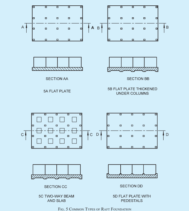
7.4.3.1 For fairly small and uniform column spacing
and when the supporting soil is not too compressible a flat concrete slab having uniform thickness throughout (a true mat) is most suitable (see Fig. 5A).
7.4.3.2 A slab may be thickened under heavy loaded columns to provide adequate strength for shear and negative moment. Pedestals may also be provided in such cases (see Fig. 5B).
7.4.3.3 A slab and beam type of raft is likely to be more economical for large column spacing and unequal column loads particularly when the supporting soil is very compressive (see Fig. 5C and Fig. 5D).
PART 6 STRUCTURAL DESIGN — SECTION 2 SOILS AND FOUNDATIONS
7.4.3.4 For very heavy structures, provision of cellular raft or rigid frames consisting of slabs and basement walls may be considered.
7.4.4 Methods of Analysis
The essential task in the analysis of a raft foundation is the determination of the distribution of contact pressure underneath the raft which is a complex function of the rigidity of the superstructure, the supporting soil and the raft itself, and cannot be determined with exactitude, except in very simple cases. This necessitates a number of simplifying assumptions to make the problem amenable to analysis. Once the distribution of contact pressure is determined, design bending moments and shears can be computed based on statics. The methods of analysis suggested are distinguished by the assumptions involved. Choice of a particular method should be governed by the validity of the assumptions in the particular case.
7.4.4.1 Rigid foundation (conventional method)
This method is based on the assumption of linear distribution of contact pressure. The basic assumptions of this method are,
a) the foundations rigid relative to the supporting soil and the compressible soil layer is relatively shallow; and
b) the contact pressure variation is assumed as planar, such that the centroid of the contact pressure coincides with the line of action of the resultant force of all loads acting on the foundation.
This method may be used when either of the following conditions is satisfied:
-
The structure behaves as rigid (due to the combined action of the superstructure and the foundation) with relative stiffness factor K>0.5 (for evaluation of K, see Annex C); and
-
The column spacing is less than 1.75/λ (see Annex C).
The raft is analyzed as a whole in each of the two perpendicular directions. The contact pressure distribution is determined by the procedure outlined in Annex D. Further analysis is also based on statics.
In the case of uniform conditions when the variations in adjacent column loads and column spacings do not exceed 20 percent of the higher value, the raft may be divided into perpendicular strips of widths equal to the distance between mid-spans and each strip may be analyzed as an independent beam with known column loads and known contact pressures. Such beams will not normally satisfy statics due to shear transfer
between adjacent strips and design may be based on suitable moment coefficients, or by moment distribution.
NOTE — On soft soils, for example, normally consolidated clays, peat, muck, organic silts, etc, the assumptions involved in the conventional method are commonly justified.