Blast Load
N-1 Blast Load
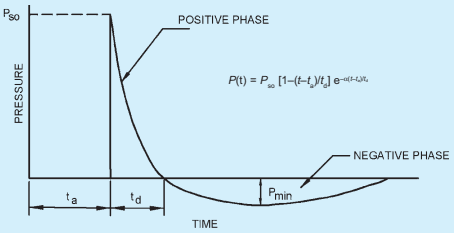
Behaviour of structures subjected to blast loads is highly complex and has to be properly understood before designing blast resistant structures. First step towards this is to compute the blast load time history acting on the structures. Magnitude of charge and its distance from the structure are the two basic parameters governing the design (Kinney and Graham, 1985). In addition to these, height of the blast charge above ground, overall length of the structure and breadth of the structure facing the shock front are also important in computation of blast loads acting on the structure. Typical time history of blast pressure is shown in Fig. 31.
N-2 Following are the steps in computation of blast load on structures:
a) Determine ground zero distance by assuming that angle between the vertical line through the point of burst and the slant line joining the burst point with the point of incidence of spherical shock on ground is between and .
b) Find whether the structure lies in regular reflection region or Mach reflection region (see Fig. 32).
c) Compute the peak over pressure, using:
where
atmospheric pressure, in MPa;
for air-burst (regular region); and
for surface-burst (Mach region).
d) Compute the positive phase duration,
For regular region using:
For a Mach region using:
e) Obtain the decay of peak overpressure with time using:
where
wave form parameter.
f) The wave form parameter is given by:
g) Compute the peak reflected pressure, acting on the structure from:
PART 6 STRUCTURAL DESIGN — SECTION 1 LOADS, FORCES AND EFFECTS
= wave form parameter;
= duration of positive phase;
weight of charge, in kg
side-on over pressure in MPa;
scaled distance, in , given by ; and
= actual/radial distance, in m, between the point of burst and point, where peak over pressure is calculated.
FIG. 31 TIME HISTORY OF BLAST PRESSURE
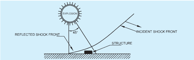
32A Structure Located in Region of Regular Reflection Surface-Burst Environment
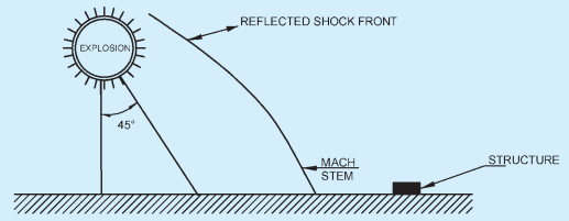
32B Structure Located in Region of Mach Reflection Surface-Burst Environment
FIG. 32 BLAST LOADING OF STRUCTURES WITH RESPECT TO LOCATION OF THE STRUCTURE
where
reflection coefficient obtained from Fig. 33.
Angle of incidence, between the line of wave propagation and outer normal of the face of the structure on which blast load acts is determined using standard procedures. If exceeds , reflection coefficient is determined as:
h) Critical distance for maximum blast effect, is given by:
where
j) Equivalent duration , of the triangular pulse is obtained by equating the impulse of exponentially decaying curve (positive phase) with that of triangular pulse
where is the positive impulse of the exponentially decaying blast time history given by:
N-3 Closed Rectangular Structures
For closed rectangular structures, Table 52 provides the blast pressure definitions for various faces of the structure due to above ground blasts.
N-4 Use of Laced Reinforced Concrete in Blast Resistant Construction
Blast resistant structures are of two types. One type is in which structure is located far from burst point and are designed for far off design range. Other type is located close to a potential explosion and falls under close-in design range. In far off design range, the blast loads are fairly uniform and deflections required to absorb the load are comparatively small. Reinforced concrete with some additional detailing are adequate to resist such loads. Close-in detonations produce non-uniform, high intensity blast loads. Local failure of structural elements is possible due to concentration of pressure at some points. For such structures, reinforced concrete is not sufficient and a material that can permit large deflections and maintain the structural integrity is required. Laced reinforced concrete has enhanced ductility and is suitable for close-in design range. Based on the duration of the impulse load, design can be either impulse design or pressure design as per J-5 and J-6, respectively.
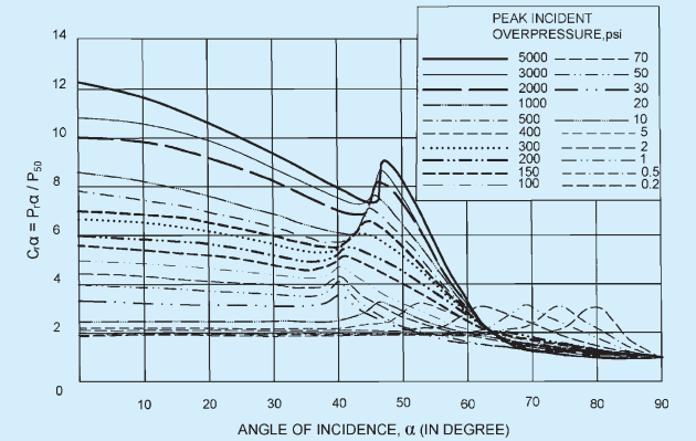
FIG. 33 VARIATION OF REFLECTION COEFFICIENT WITH ANGLE OF INCIDENCE
PART 6 STRUCTURAL DESIGN — SECTION 1 LOADS, FORCES AND EFFECTS
| Sl No.(1) | Face of the Structure1)(2) | Blast Pressure Description(3) | Blast Pressure Versus Time(4) | Parameters(5) |
| i) | Front | Peak reflected pressure, is greater of: and (see Fig. 34A and 34B) | FIG. 34A | = peak dynamic pressure to be obtained from Table 1 of good practice [6-1(30)]; = coefficient of drag to be taken from Table 2 of good practice [6-1(30)], depending upon the shape of the structure; = clearance time in which reflected pressure drops to over-pressure (= L/U).U= shock wave velocity = Ma; = Mach number of the incident pulse = ; = velocity of sound in air; = least of H and B/2. = transit time = L/U. |
| ii) | Rear | Using the pressures from actual explosion, the average loading is taken as shown in Fig. 35. | [IMAGE]FIG. 35 | |
| iii) | Sides and roof | When pulse duration, is greater than transit time of the wave from front to the sides or roof, pressure varies as shown in Fig. 36A. | FIG. 36A | |
| When pulse duration, is less than transit time of the wave from front to the sides or roof, the pressure may be considered as a moving pulse as shown in Fig. 36B. | ||||
| 1) The blast pressure definitions given in this table are valid for a closed type structure with less than 5 percent opening.2) Front face is the vertical face of the structure on which the blast wave strikes. | ||||
N-5 Impulse Design
In close-in design range, the design load can be taken as an impulse, that is, area under pressure time curve. The duration of such an impulsive load is generally small in comparison to the time period of the structural element. The criteria for impulse design is:
where is the duration of the blast load and is the time to reach the maximum response
N-6 Pressure Design
Sometimes, in the close-in design range, the duration of blast loads is also quite large. In this case, the structural element is designed for pressure. The criteria for this type of design is,
It should be clearly understood that laced reinforced concrete (LRC) construction is to be used in situations where the potential explosion site is very near to the structure. In the event of an explosion, the LRC element will serve as a barrier and will undergo plastic deformations without complete collapse. This will ensure safety of other nearby structures. Use of LRC for far off design range may prove uneconomical. Therefore, the designer should clearly analyze the situation before employing the LRC technique.
N-6.1 TNT Equivalence
Magnitude of an explosion is based on the amount of energy released. It is expressed in terms of explosion yields, which a relative measure based on TNT yield. Effective charge weight, W is expressed as:
where
weight of explosive in question,
heat of detonation of TNT.
N-7 Internal Blast Loading on Structures
Method for prediction of blast pressures due to confined explosion is summarized in Fig. 37. Pressure time variation at a point on the wall of the confinement is generated by considering both the shock wave and gas pressure loading phases. For the shock wave loading phase, it is assumed that second shock has half the amplitude and impulse of the initial reflected shock, the third shock has half the amplitude of the second shock and that all later reflections are insignificant (see Fig. 38). Durations of the reflected pulses are the same as that of the initial pulses. The time of
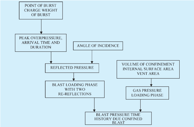
FIG. 37 METHOD FOR PREDICTION OF BLAST PRESSURE DUE TO CONFINED EXPLOSION
PART 6 STRUCTURAL DESIGN — SECTION 1 LOADS, FORCES AND EFFECTS
reverberation, that is, the time delay between the arrivals of successive reflected shocks, are nearly twice the time of arrival at the point where the blast pressures are calculated.
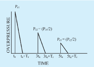
FIG. 38 REFLECTED PHASE LOADING
where
= maximum value for the quasi-static overpressure in the gas venting phase of the loading.
where
effective vent area ratio,
internal surface area of the structure,
internal volume of the structure, and
sound velocity of air.
Maximum gas overpressure, , which depends on the quantity of explosive charge, W and the internal volume of confinement, V is obtained from Fig. 40.
The value of can be obtained from:
where is given by the expression:
in which, is equal to,
Estimation of the blast parameters, namely, peak over pressure, time of arrival, time duration, is carried out using the earlier procedure. The gas venting pressure is simplified to the form shown in Fig. 39.
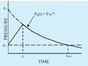
FIG. 39 GAS PRESSURE LOADING
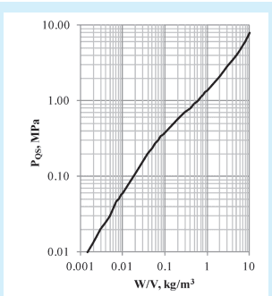
FIG. 40 PEAK QUASI-STATIC PRESSURE FOR TNT EXPLOSION IN CHAMBER
Figure 41 provides the charts for calculation of internal blast pressure for a given scaled distance.
N-8 For design of structures for blast effects of explosions above ground, see also good practice [6-1(30)].
For safety of structures during underground blasting, see also good practice [6-1(31)].
Peak overpressure ratio
Scaled arrival time (ms)
41A PEAK OVERPRESSURE RATIO
41B SCALED ARRIVAL TIME
Scaled duration (ms)
Scaled impulse (kg/m²·ms)
41C SCALED DURATION
41D SCALED IMPULSE
FIG. 41 CHARTS FOR INTERNAL BLAST PRESSURE PARAMETERS
PART 6 STRUCTURAL DESIGN — SECTION 1 LOADS, FORCES AND EFFECTS