15.1 General
A roof truss is essentially a plane structure which is very stiff in the plane of the members, that is the plane in which it is expected to carry loads, but very flexible in every other direction. Thus it can virtually be seen as a deep, narrow girder liable to buckling and twisting under loads. In order, therefore, to reduce this effect, eccentricity of loading and promote prefabrication for economy, low-pitched trussed rafters are designed with bolt ply/nail ply joints. Plywood as gussets, besides being simple have inherent constructional advantage of grain over solid wood for joints, and a better balance is achievable between the joint strength and the member strength.
Trussed rafters are light weight truss units spaced at close centres for limited spans to carry different types of roof loads. They are made from timber members of uniform thickness fastened together in one plane. The plywood gussets may be nailed or glued to the timber to form the joints. Conceptually a trussed rafter is a triangular pin jointed system, traditionally meant to carry the combined roof weight, cladding services and wind loads. There is considerable scope for saving timber by minimizing the sections through proper design without affecting structural and functional requirements.
Trussed rafters are required to be supported only at their ends so that there is no need to provide load bearing internal walls, purlins, etc. In comparison with traditional methods of construction they use less timber and considerably reduce on-site labour, and mass production of reliable units can be carried out under workshop controls.
15.2 Design
15.2.1 The design may be based on the use of Group 'C' species of standard grade timber in accordance with good practice [6-3A(7)] for nail jointed timber construction. As the strength and stiffness of any framing depends upon efficiency of joints, design calls for proper size and number of fasteners, their spacings
PART 6 STRUCTURAL DESIGN — SECTION 3 TIMBER AND BAMBOO: 3A TIMBER
| Sl No. | Character → Treatment ↓ | Compressive Parallel to Grain Tests | Tension Parallel to Grain Tests | Static Bending Tests | |||||||||||||||
| Maximum Compressive Stress (N/mm2) | Fibre Stress at EL (N/mm2) | MOE ( N/mm2) | Maximum Tensile Stress (N/mm2) | Tensile Stress at EL (N/mm2) | MOE ( N/mm2) | Edge-wise | Flat-wise | Edge-wise | Two Point Loading | ||||||||||
| Fibre Stress at EL (N/mm2) | MOR (N/mm2) | MOE ( N/mm2) | Fibre Stress at EL (N/mm2) | MOR (N/mm2) | MOE ( N/mm2) | Fibre Stress at EL (N/mm2) | MOR (N/mm2) | MOE ( N/mm2) | Fibre Stress at EL (N/mm2) | MOR (N/mm2) | MOE ( N/mm2) | ||||||||
| (1) | (2) | (3) | (4) | (5) | (6) | (7) | (8) | (9) | (10) | (11) | (12) | (13) | (14) | (15) | (16) | (17) | (18) | (19) | (20) |
| i) | UL1 | 31.196 | 16.971 | 10.202 | 30.019 | 23.446 | 10.202 | 20.993 | 29.136 | 6.769 | 39.142 | 46.401 | 8.142 | 25.114 | 28.743 | 8.044 | 32.471 | 38.553 | 9.516 |
| ii) | UL2 | 37.474 | 17.462 | 11.282 | 30.607 | 23.642 | 10.301 | 20.209 | 31.686 | 6.671 | 35.120 | 46.205 | 7.161 | 23.446 | 42.085 | 7.652 | 41.202 | 51.306 | 9.712 |
| iii) | UL3 | 35.905 | 19.914 | 10.595 | 32.667 | 23.838 | 10.006 | 22.171 | 35.022 | 6.867 | 38.750 | 47.480 | 8.437 | 25.898 | 29.234 | 7.848 | 29.626 | 38.357 | 8.633 |
| iv) | PL1 | 28.743 | 21.484 | 9.908 | 20.895 | 17.560 | 10.497 | 20.699 | 23.446 | 8.142 | 22.955 | 27.076 | 9.123 | 18.443 | 21.876 | 7.848 | 25.506 | 27.174 | 8.927 |
| v) | PL2 | 28.743 | 19.424 | 10.006 | 18.149 | 17.069 | 9.614 | 16.285 | 18.639 | 5.984 | 24.133 | 26.095 | 8.731 | 16.579 | 17.854 | 7.259 | 26.389 | 28.547 | 8.535 |
| vi) | PL3 | 27.860 | 20.111 | 9.908 | 24.721 | 19.326 | 10.497 | 15.009 | 17.069 | 7.652 | 21.680 | 26.193 | 8.829 | 10.301 | 11.183 | 6.867 | 26.487 | 30.313 | 11.183 |
| vii) | C | 35.512 | 27.959 | 10.301 | 31.490 | 23.152 | 10.104 | 25.506 | 45.518 | 7.063 | 36.788 | 57.192 | 7.063 | 31.883 | 44.537 | 7.946 | 38.161 | 52.582 | 9.221 |
| MOE — Modulus of elasticity (values rounded off for decimals) | |||||||||||||||||||
| MOR — Modulus of rupture | |||||||||||||||||||
| EL — Elastic limit | |||||||||||||||||||
| U — Urea formaldehyde with liquid hardener | |||||||||||||||||||
| P — Cold setting phenolic glue with hardener | |||||||||||||||||||
| L1 — Finger length 38 mm | |||||||||||||||||||
| L2 — Finger length 50 mm | |||||||||||||||||||
| L3 — Finger length 62 mm | |||||||||||||||||||
| C — Control (unjointed specimen) | |||||||||||||||||||
| NOTE — The information given in the above table is based on the tests conducted on glued finger joints of varying lengths/pitch with two types of adhesives. | |||||||||||||||||||
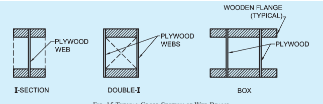
FIG. 15 TYPICAL CROSS-SECTION OF WEB BEAMS
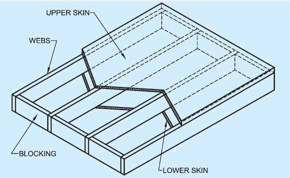
FIG. 17 STRESSED SKIN PANEL CONSTRUCTION (SINGLE SKIN OR DOUBLE SKIN)
and thickness of gusset plates for transfer of stress from one member to the other.
Trussed rafter shall be designed to sustain the dead and imposed loads specified in Part 6 ‘Structural Design, Section 1 Loads, Forces and Effects’ of the Code and the combinations expected to occur. Extra stresses/deflections during handling, transportation and erection shall be taken care of. Structural analysis, use of load-slip and moment, rotation characteristics of the individual joints may be used if feasible. Alternatively, the maximum direct force in a member may be assessed to be given by an idealized pin-jointed frame-work, fully loaded with maximum dead and imposed load in the combination in which they may reasonably be expected to occur.
NOTE — Some trussed rafters with plywood gusseted joint, span 6 m, designed in Pinus roxburghii (Chir) were tested in prototypes at Forest Research Institute, Dehra Dun for structural adequacy as under, in accordance with accepted standards [6-3A(14)],
a) destructive test (short-term); and
b) proof test (long-term).
Results demonstrated an apparent factor at safety of 4 and actual factor of safety of 3. Deflection was well within the allowable deflection at design load. A pre-camber of 1/240 of span at the bottom chord was recommended.
15.3 Timber
The species of timber including plantation grown species which can be used for trussed rafter construction and permissible stresses thereof shall be in accordance with Table 1. Moisture contents shall be as per zonal requirements in accordance with 4.4.
15.4 Plywood
Boiling water proof (BWP) grade preservative treated plywood shall be used in accordance with accepted standards [6-3A(13)]. Introduction of a plywood gusset simplifies the jointing and in addition provides rigidity to the joint. Preservation of plywood and other panel products shall be done in accordance with good practice [6-3A(15)].
15.5 Some design data on the lateral load bearing strength of common wire nails in plywood-to-wood joints are presented for timber species, Sal and Chir in Table 22, for guidance in design.