12.2.1 Stressing
12.2.1.1 The tensioning of prestressing tendons shall be carried out in a manner that will induce a smooth and even rate of increase of stress in the tendons. The prestressing shall be controlled by measuring both the force applied to the tendon and the elongation of the tendon.
Stressing schedule shall be incorporated in the design, which may include the following:
a) Details of equipment and procedure for applying prestress, specification of one end or simultaneous stressing from both ends of tendons, stressing in single stage or multiple stages, re-stressing for adjustment of force or for monitoring of force, if required, etc.
b) Calculated amount of tensile force and corresponding expected elongation of each tendon when methods described in (a) are followed.
c) Minimum requirements of strength of concrete at transfer (see also 15.2), stressing sequence
with respect to age of concrete or stage of construction, requirements with respect to grouting operations of neighbouring tendons. Method(s) of measuring force and elongation.
e) Tolerances/limits of variation from design requirements stated in (a) and (b) beyond which reference should be made to the designer. In the absence of any specified provision provided by the designer method described in 12.2.1.3 may be adopted for acceptance.
f) Assumptions made in calculation of force-elongation relationship should be given. These include effective ‘E’ value of tendon, cross sectional area of tendon, coefficient of friction and wobble factor between tendon and duct, assumed slip in anchoring devices if any, efficiency of prestressing jacks where force is measured indirectly by pressure gauges on jacks, corrections to elongation due to changes in gripping length beyond anchorages during stressing and any other relevant information.
12.2.1.2 Any slack in the prestressing tendon shall first be taken up by applying a small initial tension. The initial tension required to remove slackness shall be taken as the starting point for measuring elongation. Further increase of tension shall be carried out in suitable steps and corresponding elongations noted. The 'force-elongation' relationship shall be recorded in tabular and/or graphical form. The magnitude of initial effective elongation corresponding to initial tension applied to remove slackness shall be obtained from the recorded and linearized portion of measured tension-elongation relationship and added to the measured elongation to give the total elongation. Alternatively, the same correction can be carried out graphically as shown in Fig. 1.
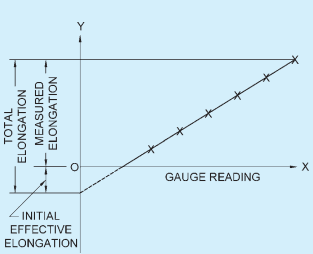
FIG. 1 DETERMINATION OF ACTUAL ELONGATION
12.2.1.3 In practice, the force and elongation of tendon may not exactly match with the expected values given in stressing schedule. In such cases either the force (or the elongation) will be achieved first and the other value lag behind. In such cases the force (or elongation) shall be further increased, but not exceeding 5 percent of the design value till the elongation (or force), which had lagged behind reaches the design value. If, even after reaching 5 percent extra value of the force (or elongation), the other lagged quantity does not reach the design value, reference should be made to the designer for review and corrective action.
12.2.1.4 When two or more prestressing wires or strands are to be tensioned simultaneously by the same tensioning apparatus, care shall be taken to ensure that all such tendons are of the same length from grip to grip.
12.2.1.5 The placement of tendons and the order of stressing and grouting shall be so arranged that the prestressing steel, when tensioned and grouted, does not adversely affect the adjoining ducts.
12.2.2 Measurement of Prestressing Force
12.2.2.1 The force induced in the prestressing tendon shall be determined by means of gauges attached to the tensioning apparatus as well as by measuring the extension of the steel. It is essential that both methods are used jointly so that the inaccuracies to which each is singly susceptible are minimized. Due allowance shall be made for the frictional losses in the tensioning apparatus.
12.2.2.2 All dynamometers and pressure gauges including master gauge shall be calibrated by an approved laboratory immediately prior to use and then at intervals not exceeding 3 months and true force determined from the calibration curve. Further, whenever there is a breakage of tendons, the calibration shall be carried out before reuse of the gauges. The pressure gauges shall be accurate within 2 percent of their full capacity.
12.2.2.3 In measuring the extension of prestressing steel, any slip which may occur in the gripping device shall be taken into consideration.
12.2.3 Breakage of Wires
The breakage of wires in anyone prestressed concrete member shall not exceed 2.5 percent during tensioning. If the breakages are more than 2.5 percent, it shall be examined and corrective actions taken. Wire breakages after anchorage, irrespective of percentage, shall not be condoned without special investigations.
12.2.4 Transfer of Prestressing Force
12.2.4.1 The transfer of the prestress shall be carried
out gradually so as to avoid large differences of tension between wires in a tendon, severe eccentricities of prestressing force and the sudden application of stress to the concrete.
12.2.4.2 Where the total prestressing force in a member is built up by successive transfers to the force of a number of individual tendons on to the concrete, account shall be taken of the effect of the successive prestressing.
12.2.4.3 In the long line and similar methods of prestressing, when the transfer is made on several moulds at a time, care shall be taken to ensure that the prestressing force is evenly applied on all the moulds, and that the transfer of prestress to the concrete is uniform along the entire length of the tension line.