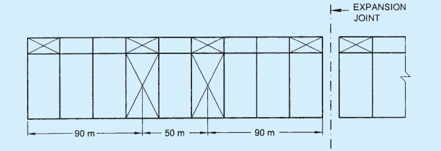
10.3.1 The structure shall be analysed in its entirety except as follows:
a) Regular building structures, with orthogonal frames in plan, may be analysed as a series of parallel two-dimensional sub-structures (part of a structure), the analysis being carried out in each of the two directions, at right angles to each other, except when there is significant load redistribution between the sub-structures (part of a structure). For earthquake loading three dimensional analysis may be necessary to account for effects of torsion and also for multi-component earthquake forces (see 5 of Part 6 ‘Structural Design, Section 1 Loads, Forces and Effects’ of the Code).
b) For vertical loading in a multi-storey building structure, provided with bracing or shear walls to resist all lateral forces, each level thereof, together with the columns immediately above and below, may be considered as a substructure, the columns being assumed fixed at the ends remote from the level under consideration.
c) Where beams at a floor level in a multi-bay building structure are considered as a substructure (part of a structure), the bending moment at the support of the beam due to gravity loads may be determined based on the assumption that the beam is fixed at the far end support, one span away from the span under consideration, provided that the floor beam is continuous beyond that support point.
10.3.2 Span Length
The span length of a flexural member in a continuous frame system shall be taken as the centre-to-centre distance between the supports.
10.3.3 Arrangements of Imposed Loads in Buildings
For building structures, the various arrangements of imposed loads considered for the analysis, shall include at least the following:
PART 6 STRUCTURAL DESIGN — SECTION 6 STEEL
a) Where the loading pattern is fixed, the arrangement concerned.
b) Where the imposed load is variable and not greater than three-quarters of the dead load, the imposed load may be taken to be acting on all spans.
c) Where the imposed load is variable and exceeds three-quarters of the dead load, arrangements of imposed load acting on the floor under consideration shall include the following cases:
-
Imposed load on alternate spans,
-
Imposed load on two adjacent spans, and
-
Imposed load on all the spans.
10.3.4 Base Stiffness
In the analysis of all structures the appropriate base stiffness about the axis under consideration shall be used. In the absence of the knowledge of the pedestal and foundation stiffness, the following may be assumed:
a) When the column is rigidly connected to a suitable foundation, the stiffness of the pedestal shall be taken as the stiffness of the column above base plate. However, in case of very stiff pedestals and foundations the column may be assumed as fixed at base.
b) When the column is nominally connected to the foundation, a pedestal stiffness of 10 percent of the column stiffness may be assumed.
c) When an actual pin or rocker is provided in the connection between the steel column and pedestal, the column is assumed as hinged at base and the pedestal and foundation may be appropriately designed for the reactions from the column.
d) In case of (a) and (b), the bottom of the pedestal shall be assumed to have the following boundary condition in the absence of any detailed procedure based on theory or tests:
-
When the foundation consist of a group of piles with a pile cap, raft foundation or an isolated footing resting on rock or very hard soil, the pedestal shall be assumed to be fixed at the level of the bottom of footing or at the top of pile cap.
-
When the foundation consists of an isolated footing resting on other soils, pedestal shall be assumed to be hinged at the level of the bottom of footing.
-
When the pedestal is supported by a single pile, which is laterally surrounded
by soil providing passive resistance, the pile shall be assumed to be fixed at a depth of 5 times the diameter of the pile below the ground level in case of compact ground or the top level of compact soil in case of poor soil overlying compact soil.
- When the column is founded into rock, it may be assumed to be fixed at the interface of the column and rock.
10.3.5 Simple Construction
Bending members may be assumed to have their ends connected for shear only and to be free to rotate. In triangulated structures, axial forces may be determined by assuming that all members are pin connected. The eccentricity for stanchion and column shall be assumed in accordance with 13.3.3.
10.3.6 Notional Horizontal Loads
To analyse a frame subjected to gravity loads, considering the sway stability of the frame, notional horizontal forces should be applied. These notional horizontal forces account for practical imperfections and should be taken at each level as being equal to 0.5 percent of factored dead load plus vertical imposed loads applied at that level. The notional load should not be applied along with other lateral loads such as wind and earthquake loads in the analysis.
10.3.6.1 The notional forces should be applied on the whole structure, in both orthogonal directions, in one direction at a time, at roof and all floor levels or their equivalent. They should be taken as acting simultaneously with factored gravity loads.
10.3.6.2 The notional force should not be,
a) applied when considering overturning or overall instability;
b) combined with other horizontal (lateral) loads;
c) combined with temperature effects, and
d) taken to contribute to the net shear on the foundation.
10.3.6.3 The sway effect using notional load under gantry load case need not be considered if the ratio of height to lateral width of the building is less than unity.