23.1 Limit State of Serviceability: Deflection
23.1.1 Type 1 and Type 2 Members
23.1.1.1 Short-term deflection
The instantaneous deflection due to design loads may be calculated using elastic analysis based on the uncracked section and the modulus of elasticity of concrete as given in 5.2.3.
23.1.1.2 Long-term deflection
The total long-term deflection due to the prestressing force, dead load and any sustained imposed load may be calculated using elastic analysis, taking into account the effects of cracking and of creep and shrinkage (see 5.2.4 and 5.2.5) Due allowance shall be made for the loss of prestress (see 18.5.2) after the period considered. The deflections should comply with the limits given in 19.3.1.
23.1.2 Type 3 Members
Where the permanent load is less than or equal to 25 percent of the design imposed load, the deflection may be calculated as in 23.1.1.1. When the permanent load is more than 25 percent of the design imposed load, the vertical deflection limits for beams and slabs may generally be assumed to be satisfied provided that the span to effective depth ratios are not greater than the values obtained as below:
a) Basic values of span to effective depth ratios for spans up to 10 m:
Cantilever : 7
Simply supported : 20
Continuous : 26
b) For spans above 10 m, the values in (a) may be multiplied by 10/(span in metres), except for cantilever in which case deflection calculations should be made.
23.2 Limit State of Serviceability: Cracking
In members made up of precast units, no tension shall be allowed at any stage at mortar or concrete joints. For a member which is free of joints, the tensile stress shall not exceed the values specified below for the 3 types of members:
a) Type 1 — No tensile stress.
b) Type 2 — The tensile stress shall not exceed 3 N/mm². However, where part of the service loads is temporary in nature, this value may be exceeded by 1.5 N/mm², provided under the permanent component of the service load the stress remains compressive.
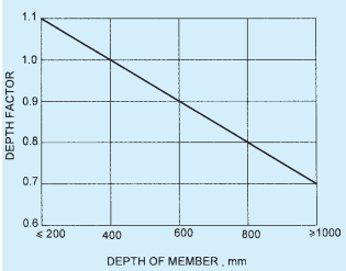
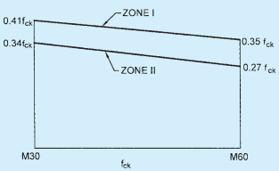
c) Type 3 — For Type 3 members in which cracking is permitted, it may be assumed that the concrete section is uncracked, and that hypothetical tensile stresses exist at the maximum size of cracks. The hypothetical tensile stresses for use in these calculations for members with either pre-tensioned or post-tensioned tendons are given in Table 10, modified by coefficients given in Fig. 6.
23.3 Limit State of Serviceability: Maximum Compression
23.3.1 Maximum Stress Under Service Conditions
PART 6 STRUCTURAL DESIGN — SECTION 5 CONCRETE: 5B PRESTRESSED CONCRETE
| Sl No. | Type of Tendons | Limiting Crack Width mm | Stress of Concrete for Grade | ||||
| M 30 | M 35 | M 40 | M 45 | M 50 and above | |||
| (1) | (2) | (3) | (4) | (5) | (6) | (7) | (8) |
| i) | Pre-tensioned tendons | 0.1 | — | — | 4.1 | 4.4 | 4.8 |
| 0.2 | — | — | 5.0 | 5.4 | 5.8 | ||
| ii) | Grouted post- tensioned tendons | 0.1 | 3.2 | 3.6 | 4.1 | 4.4 | 4.8 |
| 0.2 | 3.8 | 4.4 | 5.0 | 5.4 | 5.8 | ||
| iii) | Pre-tensioned tendons distributed in the tensile zone and positioned close to the tension faces of concrete. | 0.1 | — | — | 5.3 | 5.8 | 6.3 |
| 0.2 | — | — | 6.3 | 6.8 | 7.3 | ||
NOTE — When additional reinforcement is distributed within the tension zone and positioned close to the tension face of concrete, the hypothetical tensile stresses may be increased by an amount which is proportional to the cross sectional areas of the additional reinforcement expressed as a percentage of the cross sectional area of the concrete. For 1 percent of additional reinforcement, the stress may be increased by for members with pre-tensioned and grouted post-tensioned tendons and by for other members. For other percentages of additional reinforcement the stresses may be increased in proportion excepting that the total hypothetical tensile stress shall not exceed 0.25 times the characteristic compressive strength of concrete.