H-4.1 Equivalent cantilever approach gives a simple
| Sl No. | Type of Pile Behaviour | Relation of Embedded Length with Stiffness Factor | |
| Linearly Increasing (3) | Constant (4) | ||
| (1) | (2) | ||
| i) | Short (rigid) pile | ||
| ii) | Long (elastic) pile | ||
NOTE — The intermediate shall indicate a case between rigid pile behaviour and elastic pile behaviour.
procedure for obtaining the deflections and moments due to relatively small lateral loads. This requires the determination of depth of virtual fixity, .
The depth to the point of fixity may be read from the plots given in Fig. 14. 'e' is the effective eccentricity of the point of load application obtained either by converting the moment to an equivalent horizontal load or by actual position of the horizontal load application. R and T are the stiffness factors described earlier.
H-4.2 The pile head deflection, shall be computed using the following equations:

PART 6 STRUCTURAL DESIGN — SECTION 2 SOILS AND FOUNDATIONS
Deflection, (for fixed head pile)
where
lateral load, in ;
deflection of pile head, in mm;
Young's modulus of pile material, in ;
moment of inertia of the pile cross-section, in ;
depth to point of fixity, in m; and
e = cantilever length above ground/bed to the point of load application, in m.
H-4.3 The fixed end moment of the pile for the equivalent cantilever may be determined from the following expressions:
Fixed end moment, (for free head pile)
Fixed end moment, (for fixed head pile)
The fixed head moment, of the equivalent cantilever is higher than the actual maximum moment in the pile. The actual maximum moment may be obtained by multiplying the fixed end moment of the equivalent cantilever by a reduction factor, , given in Fig. 15.
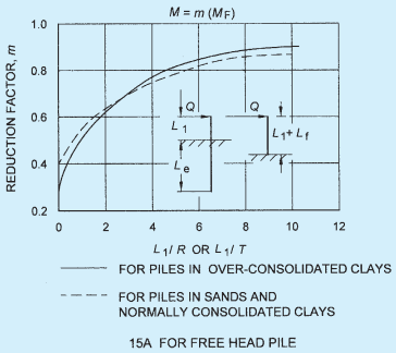
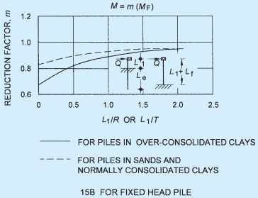
FIG. 15 DETERMINATION OF REDUCTION FACTORS FOR COMPUTATION OF MAXIMUM MOMENT IN PILE