Reinforcing steel of same type and grade shall be used as main reinforcement in a structural member. However, simultaneous use of two different types or grades of steel for main and secondary reinforcement respectively is permissible.
25.1.1 Bars may be arranged singly, or in pairs in contact, or in groups of three or four bars bundled in contact. Bundled bars shall be enclosed within stirrups or ties. Bundled bars shall be tied together to ensure the bars remaining together. Bars larger than 32 mm diameter shall not be bundled, except in columns. Congestion of reinforcement should be avoided during detailing. Various methods such as choosing the diameter and grade of steel carefully and bundling of reinforcement, if required, are available.
25.1.2 The recommendations for detailing for earthquake-resistant construction given in Annex F should be taken into consideration, where applicable (see also 8 of Part 6 ‘Structural Design, Section 4 Masonry’ of the Code).
PART 6 STRUCTURAL DESIGN — SECTION 5 CONCRETE: 5A PLAIN AND REINFORCED CONCRETE
25.2Development of Stress in Reinforcement
The calculated tension or compression in any bar at any section shall be developed on each side of the section by an appropriate development length or end anchorage or by a combination thereof.
25.2.1 Development Length of Bars
The development length Ld is given by:
Ld=4τbdϕσs
where
ϕ= nominal diameter of the bar,
σs=stress in bar at the section considered at design load, and
τbd= design bond stress given in 25.2.1.1.
NOTES
1 The development length includes anchorage values of hooks in tension reinforcement.
2 For bars of sections other than circular, the development length should be sufficient to develop the stress in the bar by bond.
3 For plain cement concrete of M 15 grade with nominal reinforcement, the design bond stress may be taken as 1.0N/mm2 .
25.2.1.1 Design bond stress in limit state method for plain bars in tension shall be as below:
Grade of Concrete
M 20
M 25
M 30
M 35
M 40 and above
Design Bond
1.2
1.4
1.5
1.7
1.9
Stress, τbd, N/mm2
For deformed bars conforming to accepted standard [6-5A(36)] these values shall be increased by 60 percent.
For fusion bonded epoxy coated deformed bars conforming to accepted standard [6-5A(37)], design bond stress values shall be taken as 80 percent of the values given in the above table.
For bars in compression, the values of bond stress for bars in tension shall be increased by 25 percent.
The values of bond stress in working stress design, are given in B-2.1.
25.2.1.2 Bars bundled in contact
The development length of each bar of bundled bars shall be that for the individual bar, increased by 10 percent for two bars in contact, 20 percent for three bars in contact and 33 percent for four bars in contact.
25.2.2 Anchoring Reinforcing Bars
25.2.2.1 Anchoring bars in tension
a) Deformed bars may be used without end anchorages provided development length requirement is satisfied. Hooks should normally be provided for plain bars in tension.
b) Bends and hooks — Bends and hooks shall conform to good practice [6-5A(29)] :
Bends — The anchorage value of bend shall be taken as 4 times the diameter of the bar for each 45∘ bend subject to a maximum of 16 times the diameter of the bar.
Hooks — The anchorage value of a standard U-type hook shall be equal to 16 times the diameter of the bar.
25.2.2.2 Anchoring bars in compression
The anchorage length of straight bar in compression shall be equal to the development length of bars in compression as specified in 25.2.1. The projected length of hooks, bends and straight lengths beyond bends, if provided for a bar in compression, shall only be considered for development length.
25.2.2.3 Mechanical devices for anchorage
Any mechanical or other device capable of developing the strength of the bar without damage to concrete may be used as anchorage with the approval of the Engineer-in-Charge.
25.2.2.4 Anchoring shear reinforcement
a) Inclined bars — The development length shall be as for bars in tension; this length shall be measured as under:
In tension zone, from the end of the sloping or inclined portion of the bar, and
In the compression zone, from the mid depth of the beam.
b) Stirrups — Notwithstanding any of the provisions of this standard, in case of secondary reinforcement, such as stirrups and transverse ties, complete development lengths and anchorage shall be deemed to have been provided when the bar is bent through an angle of at least 90∘ round a bar of at least its own diameter and is continued beyond the end of the curve for a length of at least eight diameters, or when the bar is bent through an angle of 135∘ and is continued beyond the end of the curve for a length of at least six bar diameters or when the bar is bent through an angle of 180∘ and is continued beyond the end of the curve for a length of at least four bar diameters.
25.2.2.5 Bearing stresses at bends
The bearing stress in concrete for bends and hooks described in good practice [6-5A(29)] need not be checked. The bearing stress inside a bend in any other bend shall be calculated as given below:
Bearing stress=rϕFbt
where
Fbt = tensile force due to design loads in a bar or group or bars,
r= internal radius of the bend, and
ϕ= size of the bar or, in bundle, the size of bar of equivalent area.
For limit state method of design, this stress shall not 1.5f1.
exceed 1+a2ϕ1.5fck where fck is the characteristic cube
strength of concrete and a, for a particular bar or group of bars in contact shall be taken as the centre-to-centre distance between bars or groups of bars perpendicular to the plane of the bend; for a bar or group of bars adjacent to the face of the member a shall be taken as the cover plus size of bar (ϕ). For working stress method
of design, the bearing stress shall not exceed 1+a2ϕfck .
25.2.2.6 If a change in direction of tension or compression reinforcement induces a resultant force acting outward tending to split the concrete, such force should be taken up by additional links or stirrups. Bent tension bar at a re-entrant angle should be avoided.
25.2.3 Curtailment of Tension Reinforcement in Flexural Members
25.2.3.1 For curtailment, reinforcement shall extend beyond the point at which it is no longer required to resist flexure for a distance equal to the effective depth of the member or 12 times the bar diameter, whichever is greater except at simple support or end of cantilever. In addition 25.2.3.2 to 25.2.3.5 shall also be satisfied.
NOTE — A point at which reinforcement is no longer required to resist flexure is where the resistance moment of the section, considering only the continuing bars, is equal to the design moment.
25.2.3.2 Flexural reinforcement shall not be terminated in a tension zone unless any one of the following conditions is satisfied:
a) The shear at the cut-off point does not exceed two-thirds that permitted, including the shear strength of web reinforcement provided.
b) Stirrup area in excess of that required for shear and torsion is provided along each terminated bar over a distance from the cut-off point equal to three-fourths the effective depth of the member. The excess stirrup area shall be not less than 0.4bs/fy , where b is the breadth of beam, s is the spacing and fy is the characteristic strength of reinforcement in N/mm 2 . The resulting spacing shall not exceed d/8βb where βb is the ratio of the area of bars cut-off to the total area of bars at the section, and d is the effective depth.
c) For 36 mm and smaller bars, the continuing bars provide double the area required for flexure at the cut-off point and the shear does not exceed three-fourths that permitted.
25.2.3.3 Positive moment reinforcement
a) At least one-third the positive moment reinforcement in simple members and one-fourth the positive moment reinforcement in continuous members shall extend along the same face of the member into the support, to a length equal to Ld/3 .
b) When a flexural member is part of the primary lateral load resisting system, the positive reinforcement required to be extended into the support as described in (a) shall be anchored to develop its design stress in tension at the face of the support.
c) At simple supports and at points of inflection, positive moment tension reinforcement shall be limited to a diameter such that Ld computed for fd by 25.2.1 does not exceed:
VM1+L0
where
M1=moment of resistance of the section assuming all reinforcement at the section to be stressed to fd;
fd = 0.87 fy in the case of limit state design and the permissible stress σst in the case of working stress design;
V= shear force at the section due to design loads;
L0 = sum of the anchorage beyond the centre of the support and the equivalent anchorage value of any hook or mechanical anchorage at simple support; and at a point of inflection, L0 is limited to the effective depth of the members or 12ϕ , whichever is greater; and
ϕ= diameter of bar.
PART 6 STRUCTURAL DESIGN — SECTION 5 CONCRETE: 5A PLAIN AND REINFORCED CONCRETE
The value of M1/V in the above expression may be increased by 30 percent when the ends of the reinforcement are confined by a compressive reaction.
25.2.3.4 Negative moment reinforcement
At least one-third of the total reinforcement provided for negative moment at the support shall extend beyond the point of inflection for a distance not less than the effective depth of the member of 12ϕ or one-sixteenth of the clear span, whichever is greater.
25.2.3.5 Curtailment of bundled bars
Bars in a bundle shall terminate at different points spaced apart by not less than 40 times the bar diameter except for bundles stopping at a support.
25.2.4 Special Members
Adequate end anchorage shall be provided for tension reinforcement in flexural members where reinforcement stress is not directly proportional to moment, such as sloped, stepped, or tapered footings; brackets; deep beams; and members in which the tension reinforcement is not parallel to the compression face.
25.2.5 Reinforcement Splicing
Where splices are provided in the reinforcing bars, they shall as far as possible be away from the sections of maximum stress and be staggered. It is recommended that splices in flexural members should not be at sections where the bending moment is more than 50 percent of the moment of resistance; and not more than half the bars shall be spliced at a section.
Where more than one-half of the bars are spliced at a section or where splices are made at points of maximum stress, special precautions shall be taken such as increasing the length of lap and/or using spirals or closely-spaced stirrups around the length of the splice.
25.2.5.1 Lap splices
a) Lap splices shall not be used for bars larger than 32 mm. Bars larger than 32 mm shall be welded (see 11.4) or mechanically spliced.
b) Lap splices shall be considered as staggered if the centre-to-centre distance of the splices is not less than 1.3 times the lap length calculated as described in (c).
c) Lap length including anchorage value of hooks for bars in flexural tension shall be Ld (see 25.2.1) or 30 φ, whichever is greater. The straight length of the lap shall not be less than 15 φ or 200 mm. The following provisions shall also apply:
Where lap occurs for a tension bar located at,
top of a section as cast and the minimum cover is less than twice the diameter of
the lapped bar, the lap length shall be increased by a factor of 1.4.
corner of a section and the minimum cover to either face is less than twice the diameter of the lapped bar or where the clear distance between adjacent laps is less than 75 mm or 6 times the diameter of lapped bar, whichever is greater, the lap length should be increased by a factor of 1.4.
Where both condition (1) and (2) apply, the lap length should be increased by a factor of 2.0.
NOTE — Splices in tension members shall be enclosed in spirals made of bars not less than 6 mm diameter with pitch not more than 100 mm.
d) The lap length in compression shall be equal to the development length in compression, calculated as described in 25.2.1, but not less than 24ϕ.
e) When bars of two different diameters are to be spliced, the lap length shall be calculated on the basis of diameter of the smaller bar.
f) When splicing of welded wire fabric is to be carried out, lap splices of wires shall be made so that overlap measured between the extreme cross wires shall be not less than the spacing of cross wires plus 100 mm.
g) In case of bundled bars, lapped splices of bundled bars shall be made by splicing one bar at a time; such individual splices within a bundle shall be staggered.
Reinforcement couplers for mechanical splices of bars for concrete reinforcement, used, shall be in accordance with accepted standard [6-5A(38)].
25.2.5.2 Strength of welds
The following values may be used where the strength of the weld has been proved by tests to be at least as great as that of the parent bar.
a) Splices in compression — For welded splices and mechanical connection, 100 percent of the design strength of joined bars.
b) Splices in tension
80 percent of the design strength of welded bars (100 percent if welding is strictly supervised and if at any cross-section of the member not more than 20 percent of the tensile reinforcement is welded).
100 percent of design strength of mechanical connection.
25.2.5.3 End-bearing splices
End-bearing splices shall be used only for bars in
compression. The ends of the bars shall be square cut and concentric bearing ensured by suitable devices.
25.3Spacing of Reinforcement
25.3.1 For the purpose of this clause, the diameter of a round bar shall be its nominal diameter, and in the case of bars which are not round or in the case of deformed bars or crimped bars, the diameter shall be taken as the diameter of a circle giving an equivalent effective area. Where spacing limitations and minimum concrete cover (see 25.4) are based on bar diameter, a group of bars bundled in contact shall be treated as a single bar of diameter derived from the total equivalent area.
25.3.2 Minimum Distance Between Individual Bars
The following shall apply for spacing of bars:
a) The horizontal distance between two parallel main reinforcing bars shall usually be not less than the greatest of the following :
The diameter of the bar if the diameters are equal.
The diameter of the larger bar if the diameters are unequal, and
5 mm more than the nominal maximum size of coarse aggregate.
NOTE — This does not preclude the use of larger size of aggregates beyond the congested reinforcement in the same member; the size of aggregates may be reduced around congested reinforcement to comply with this provision.
b) Greater horizontal distance than the minimum specified in (a) should be provided, wherever possible. However, when needle vibrators are used the horizontal distance between bars of a group may be reduced to two-thirds the nominal maximum size of the coarse aggregate, provided that sufficient space is left between groups of bars to enable the vibrator to be immersed.
c) Where there are two or more rows of bars, the bars shall be vertically in line and the minimum vertical distance between the bars shall be 15 mm, two-thirds the nominal maximum size of aggregate or the maximum size of bars, whichever is greater.
25.3.3 Maximum Distance Between Bars in Tension
Unless the calculation of crack widths shows that a greater spacing is acceptable, the following rules shall be applied to flexural members in normal internal or external conditions of exposure:
a) Beams — The horizontal distance between parallel reinforcement bars, or groups, near
the tension face of a beam shall not be greater than the value given in Table 15 depending on the amount of redistribution carried out in analysis and the characteristic strength of the reinforcement.
b) Slabs
The horizontal distance between parallel main reinforcement bars shall not be more than three times the effective depth of solid slab or 300 mm, whichever is smaller.
The horizontal distance between parallel reinforcement bars provided against shrinkage and temperature shall not be more than five times the effective depth of a solid slab or 300 mm, whichever is smaller.
Table 15Clear Distance Between Bars (Clause 25.3.3)
Sl No.
fy
Percentage Redistribution to or from Section Considered
-30
-15
0
+15
+30
Clear Distance Between Bars
(1)
N/mm2(2)
mm(3)
mm(4)
mm(5)
mm(6)
mm(7)
i)
250
215
260
300
300
300
ii)
415
125
155
180
210
235
iii)
500
105
130
150
175
195
NOTE — The spacings given in table are not applicable to members subjected to particularly aggressive environments unless in the calculation of the moment of resistance fy has been limited to 300 N/mm 2 in limit state design and σst limited to 165 N/mm 2 in working stress design.
25.4Nominal Cover to Reinforcement
25.4.1 Nominal Cover
Nominal cover is the design depth of concrete cover to all steel reinforcements, including links. It is the dimension used in design and indicated in the drawings. It shall be not less than the diameter of the bar.
25.4.2 Nominal Cover to Meet Durability Requirement
Minimum values for the nominal cover of normal-weight aggregate concrete which should be provided to all reinforcement, including links depending on the condition of exposure described in 7.2.2 shall be as given in Table 16.
25.4.2.1 However, for a longitudinal reinforcing bar in a column nominal cover shall in any case not be less than 40 mm, or less than the diameter of such bar. In the case of columns of minimum dimension of 200 mm or under, whose reinforcing bars do not exceed 12 mm, a nominal cover of 25 mm may be used.
PART 6 STRUCTURAL DESIGN — SECTION 5 CONCRETE: 5A PLAIN AND REINFORCED CONCRETE
3 For exposure condition ‘severe’ and ‘very severe’, reduction of 5 mm may be made, where concrete grade is M 35 and above.
Table 16Nominal Cover to Meet Durability Requirements (Clause 25.4.2)
Sl No.
Exposure
Nominal Concrete Cover not Less Than mm
(1)
(2)
(3)
i)
Mild
20
ii)
Moderate
30
iii)
Severe
45
iv)
Very severe
50
v)
Extreme
75
NOTES
1 For main reinforcement up to 12mm diameter bar for mild exposure the nominal cover may be reduced by 5mm.
2 Unless specified otherwise, actual concrete cover should not deviate from the required nominal cover by −0+10 mm.
25.4.2.2 For footings minimum cover shall be 50 mm.
25.4.3 Nominal Cover to Meet Specified Period of Fire Resistance
Minimum values of nominal cover of normal-weight aggregate concrete to be provided to all reinforcement including links to meet specified period of fire resistance shall be given in Table 16A.
25.5Requirements of Reinforcement for Structural Members
25.5.1 Beams
25.5.1.1 Tension reinforcement
a) Minimum reinforcement – The minimum area of tension reinforcement shall be not less than that given by the following:
bdAs=fy0.85
where
As= minimum area of tension reinforcement;
b = breadth of beam or the breadth of the web of T-beam;
d= effective depth, and
fy= characteristic strength of reinforcement, in N/mm2
b) Maximum reinforcement – The maximum area of tension reinforcement shall not exceed 0.04 bD.
where
D = overall depth of beam or slab or diameter of column; dimension of a rectangular column in the direction under consideration.
NOTE — The use of 4 percent reinforcement may involve practical difficulty in placing and compacting concrete; hence lower percentage is recommended.
25.5.1.2 Compression reinforcement
The maximum area of compression reinforcement shall not exceed 0.04 bD. Compression reinforcement in beams shall be enclosed by stirrups for effective lateral restraint. The arrangement of stirrups shall be as specified in 25.5.3.2.
NOTE — The use of 4 percent reinforcement may involve practical difficulty in placing and compacting concrete; hence lower percentage is recommended.
25.5.1.3 Side face reinforcement
Where the depth of the web in a beam exceeds 750 mm, side face reinforcement shall be provided along the two faces. The total area of such reinforcement shall be not
Table 16ANominal Cover to Meet Specified Period of Fire Resistance (Clauses 20.4, 25.4.3 and Fig. 1)
Sl No.
Fire Resistance
Nominal Cover
Beams
Slabs
Ribs
Columns
Simply Supported mm (3)
Continuous mm (4)
Simply Supported mm (5)
Continuous mm (6)
Simply Supported mm (7)
Continuous mm (8)
mm (9)
(1)
h (2)
i)
0.5
20
20
20
20
20
20
40
ii)
1
20
20
20
20
20
20
40
iii)
1.5
20
20
25
20
35
20
40
iv)
2
40
30
35
25
45
35
40
v)
3
60
40
45
35
55
45
40
vi)
4
70
50
55
45
65
55
40
NOTES
1 The nominal covers given relate specifically to the minimum member dimensions given in Fig. 1.
2 Cases that lie below the bold line require attention to the additional measures necessary to reduce the risks of spalling (see 20.3.1).
less than 0.1 percent of the web area and shall be distributed equally on two faces at a spacing not exceeding 300mm or web thickness, whichever is less.
25.5.1.4 Transverse reinforcement in beams for shear and torsion
The transverse reinforcement in beams shall be taken around the outer-most tension and compression bars. In T-beams and I-beams, such reinforcement shall pass around longitudinal bars located close to the outer face of the flange.
25.5.1.5 Maximum spacing of shear reinforcement
The maximum spacing of shear reinforcement measured along the axis of the member shall not exceed 0.75 d for vertical stirrups and d for inclined stirrups at 45∘ , where d is the effective depth of the section under consideration. In no case shall the spacing exceed 300 mm.
25.5.1.6 Minimum shear reinforcement
Minimum shear reinforcement in the form of stirrups shall be provided such that,
bsvAsv≥0.87fy0.4
where
Asv= total cross-sectional area of stirrups legs effective in shear,
sv = stirrup spacing along the length of the member,
b = breadth of the beam or breadth of the web of flanged beam, and
fy = characteristic strength of the stirrup reinforcement, in N/mm 2 , which shall not be taken greater than 415 N/mm 2 .
Where the maximum shear stress calculated is less than half the permissible value and in members of minor structural importance such as lintels, this provision need not be complied with.
25.5.1.7 Distribution of torsion reinforcement
When a member is designed for torsion (see 40 or B-6) torsion reinforcement shall be provided as below:
a) The transverse reinforcement for torsion shall be rectangular closed stirrups placed perpendicular to the axis of the member. The spacing of the stirrups shall not exceed the least of x1, 4x1+y1, and 300 mm, where x1 and y1 are respectively the short and long dimensions of the stirrup.
b) Longitudinal reinforcement shall be placed as
close as is practicable to the corners of the cross-section and in all cases, there shall be at least one longitudinal bar in each corner of the ties. When the cross-sectional dimension of the member exceeds 450 mm, additional longitudinal bars shall be provided to satisfy the requirements of minimum reinforcement and spacing given in 25.5.1.3.
25.5.1.8 Reinforcement in flanges of T-beams and L-beams shall satisfy the requirements in 22.1.1(b). Where flanges are in tension, a part of the main tension reinforcement shall be distributed over the effective flange width or a width equal to one-tenth of the span, whichever is smaller. If the effective flange width exceeds one-tenth of the span, nominal longitudinal reinforcement shall be provided in the outer portions of the flange.
25.5.2 Slabs
The rules given in 25.5.2.1 and 25.5.2.2 shall apply to slabs in addition to those given in the appropriate clauses.
25.5.2.1 Minimum reinforcement
The mild steel reinforcement in either direction in slabs shall not be less than 0.15 percent of the total cross-sectional area. However, this value can be reduced to 0.12 percent when high strength deformed bars or welded wire fabric are used.
25.5.2.2 Maximum diameter
The diameter of reinforcing bars shall not exceed one-eighth of the total thickness of the slab.
25.5.3 Columns
25.5.3.1 Longitudinal reinforcement
a) The cross-sectional area of longitudinal reinforcement, shall be not less than 0.8 percent nor more than 6 percent of the gross cross-sectional area of the column.
NOTE — The use of 6 percent reinforcement may involve practical difficulties in placing and compacting of concrete; hence lower percentage is recommended. Where bars from the columns below have to be lapped with those in the column under consideration, the percentage of steel shall usually not exceed 4 percent.
b) In any column that has a larger cross-sectional area than that required to support the load, the minimum percentage of steel shall be based upon the area of concrete required to resist the direct stress and not upon the actual area.
c) The minimum number of longitudinal bars provided in a column shall be four in rectangular columns and six in circular columns.
PART 6 STRUCTURAL DESIGN — SECTION 5 CONCRETE: 5A PLAIN AND REINFORCED CONCRETE
d) The bars shall not be less than 12 mm in diameter.
e) A reinforced concrete column having helical reinforcement shall have at least six bars of longitudinal reinforcement within the helical reinforcement.
f) In a helically reinforced column, the longitudinal bars shall be in contact with the helical reinforcement and equidistant around its inner circumference.
g) Spacing of longitudinal bars measured along the periphery of the column shall not exceed 300 mm.
h) In case of pedestals in which the longitudinal reinforcement is not taken in account in strength calculations, nominal longitudinal reinforcement not less than 0.15 percent of the cross-sectional area shall be provided.
NOTE — Pedestal is a compression member, the effective length of which does not exceed three times the least lateral dimension.
25.5.3.2 Transverse reinforcement
a) General — A reinforced concrete compression member shall have transverse or helical reinforcement so disposed that every longitudinal bar nearest to the compression face has effective lateral support against buckling subject to provisions in (b). The effective lateral support is given by transverse reinforcement either in the form of circular rings capable of taking up circumferential tension or by polygonal links (lateral ties) with internal angles not exceeding 135∘ . The ends of the transverse reinforcement shall be properly anchored [see 25.2.2.4(b)].
b) Arrangement of transverse reinforcement
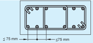
If the longitudinal bars are not spaced more than 75 mm on either side, transverse reinforcement need only to go round corner and alternate bars for the purpose of providing effective lateral supports (see Fig. 8).
FIG. 8
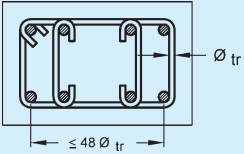
If the longitudinal bars spaced at a distance of not exceeding 48 times the
diameter of the tie are effectively tied in two directions, additional longitudinal bars in between these bars need to be tied in one direction by open ties (see Fig. 9).
FIG. 9
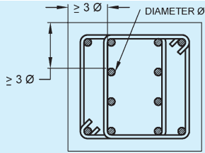
Where the longitudinal reinforcing bars in a compression member are placed in more than one row, effective lateral support to the longitudinal bars in the inner rows may be assumed to have been provided, if
i) transverse reinforcement is provided for the outer-most row in accordance with 25.5.3.2; and
ii) no bar of the inner row is closer to the nearest compression face than three times the diameter of the largest bar in the inner row (see Fig. 10).
FIG. 10
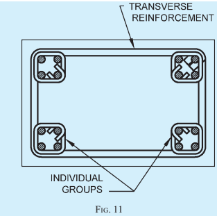
Where the longitudinal bars in a compression member are grouped (not in contact) and each group adequately tied with transverse reinforcement in accordance with 25.5.3.2, the transverse reinforcement for the compression member as a whole may be provided on the assumption that each group is a single longitudinal bar for purpose of determining the pitch and diameter of the transverse reinforcement in accordance with 25.5.3.2. The diameter of such
transverse reinforcement need not, however, exceed 20mm (see Fig. 11).
c) Pitch and diameter of lateral ties
Pitch — The pitch of transverse reinforcement shall be not more than the least of the following distances:
i) The least lateral dimension of the compression members;
ii) Sixteen times the smallest diameter of the longitudinal reinforcement bar to be tied; and
iii) 300mm.
Diameter — The diameter of the polygonal links or lateral ties shall be not less than one-fourth of the diameter of the largest longitudinal bar, and in no case less than 6 mm.
d) Helical reinforcement
Pitch — Helical reinforcement shall be of regular formation with the turns of the helix spaced evenly and its ends shall be anchored properly by providing one and a half extra turns of the spiral bar. Where an increased load on the column on the strength of the helical reinforcement is allowed for, the pitch of helical turns shall be not more than 75 mm, nor more than one-sixth of the core diameter of the column, nor less than 25 mm, nor less than three times the diameter of the steel bar forming the helix. In other cases, the requirements of 25.5.3.2 shall be complied with.
The diameter of the helical reinforcement shall be in accordance with 25.5.3.2 (c) (2).
25.5.3.3 In columns where longitudinal bars are offset at a splice, the slope of the inclined portion of the bar with the axis of the column shall not exceed 1 in 6, and the portions of the bar above and below the offset shall be parallel to the axis of the column. Adequate horizontal support at the offset bends shall be treated as a matter of design, and shall be provided by metal ties, spirals, or parts of the floor construction. Metal ties or spirals so designed shall be placed near (not more than eight-bar diameters from) the point of bend. The horizontal thrust to be resisted shall be assumed as one and half times the horizontal components of the nominal stress in the inclined portion of the bar. Offset bars shall be bent before they are placed in the forms. Where column faces are offset 75 mm or more, splices of vertical bars adjacent to the offset face shall be made by separate dowels overlapped as specified in 25.2.5.1.
26 EXPANSION JOINTS
26.1 Structures in which marked changes in plan dimensions take place abruptly shall be provided with expansion joints at the section where such changes occur. Expansion joints shall be so provided that the necessary movement occurs with a minimum resistance at the joint. The structures adjacent to the joint should preferably be supported on separate columns or walls but not necessarily on separate foundations. Reinforcement shall not extend across an expansion joint and the break between the sections shall be complete.
26.2 The details as to the length of a structure where expansion joints have to be provided can be determined after taking into consideration various factors, such as temperature, exposure to weather, the time and season of the laying of the concrete, etc. Normally structures exceeding 45 m in length are designed with one or more expansion joints. However, in view of the large number of factors involved in deciding the location, spacing and nature of expansion joints, the provision of expansion joint in reinforced cement concrete structures should be left to the discretion of the designer. Good practice [6-5A(39)] gives the design considerations, which need to be examined and provided for.
Section 5A (D) Special Design Requirements for Structural Members and Systems