13.6.1 General
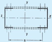
13.6.1.1 Members comprising two main components laced and tied, should where practicable, have a radius of gyration about the axis perpendicular to the plane of lacing not less than the radius of gyration about the axis parallel to the plane of lacing [see Fig.10A and Fig. 10B].
13.6.1.2 As far as practicable, the lacing system shall be uniform throughout the length of the column.
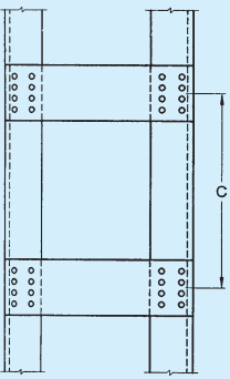
13.6.1.3 Except for tie plates as specified in 13.7, double laced systems [see Fig. 10B] and single laced systems [see Fig. 10A] on opposite sides of the main components shall not be combined with cross members (ties) perpendicular to the longitudinal axis of the strut [see Fig. 10C], unless all forces resulting from deformation of the strut members are calculated and provided for in the design of lacing and its fastenings.
13.6.1.4 Single laced systems, on opposite faces of the components being laced together shall preferably be in the same direction so that one is the shadow of the other, instead of being mutually opposed in direction.
13.6.1.5 The effective slenderness ratio, (KL/r)e , of laced columns shall be taken as 1.05 times the (KL/r)0 , the actual maximum slenderness ratio, in order to account for shear deformation effects.
13.6.2 Width of Lacing Bars
In bolted/riveted construction, the minimum width of lacing bars shall be three times the nominal diameter of the end bolt/rivet.
13.6.3 Thickness of Lacing Bars
The thickness of flat lacing bars shall not be less than one-fortieth of its effective length for single lacings and one-sixtieth of the effective length for double lacings.
13.6.3.1 Rolled sections or tubes of equivalent strength may be permitted instead of flats, for lacings.
13.6.4 Angle of Inclination
Lacing bars, whether in double or single systems, shall be inclined at an angle not less than 40∘ nor more than 70∘ to the axis of the built-up member.
13.6.5 Spacing
13.6.5.1 The maximum spacing of lacing bars, whether connected by bolting, riveting or welding, shall also be such that the maximum slenderness ratio of the components of the main member (a1/r1), between consecutive lacing connections is not greater than 50 or 0.7 times the most unfavourable slenderness ratio of the member as a whole, whichever is less, where a1 is the unsupported length of the individual member between lacing points, and r1 is the minimum radius of gyration of the individual member being laced together.
13.6.5.2 Where lacing bars are not lapped to form the connection to the components of the members, they shall be so connected that there is no appreciable interruption in the triangulation of the system.
13.6.6 Design of Lacings
13.6.6.1 The lacing shall be proportioned to resist a total transverse shear, Vt , at any point in the member, equal to at least 2.5 percent of the axial force in the member and shall be divided equally among all transverse-lacing systems in parallel planes.
13.6.6.2 For members carrying calculated bending stress due to eccentricity of loading, applied end moments and/or lateral loading, the lacing shall be proportioned to resist the actual shear due to bending, in addition to that specified in 13.6.6.1.
13.6.6.3 The slenderness ratio, KL/r, of the lacing bars shall not exceed 145. In bolted/riveted construction, the effective length of lacing bars for the determination of the design strength shall be taken as the length between the inner end fastener of the bars for single lacing, and as 0.7 of this length for double lacings effectively connected at intersections. In welded construction, the effective lengths shall be taken as 0.7 times the distance between the inner ends of welds connecting the single lacing bars to the members.
NOTE — The required section for lacing bars as compression/tension members shall be determined by using the appropriate design stresses, fcd subject to the requirements in 13.6.3 to 13.6.6 and Td in 12.1.
13.6.7 Attachment to Main Members
The bolting, riveting or welding of lacing bars to the main members shall be sufficient to transmit the force calculated in the bars. Where welded lacing bars overlap the main members, the amount of lap measured along either edge of the lacing bar shall be not less than four times the thickness of the bar or the thickness of the element of the members to which it is connected,

10C Double Laced and Single Laced System Combined with Cross Members
FIG. 10 TOP RESTRAINT CONDITIONS
PART 6 STRUCTURAL DESIGN — SECTION 6 STEEL
whichever is less. The welding should be sufficient to transmit the load in the bar and shall, in any case, be provided along each side of the bar for the full length of lap.
13.6.8 End Tie Plates
Laced compression members shall be provided with tie plates as per 13.7 at the ends of lacing systems and at intersection with other members/stays and at points where the lacing systems are interrupted.